nicksydney
Junior Member level 3
Hi,
Sorry if I'm posting in the wrong thread and feel free to move my post to the appropriate thread.
I'm trying to learn more about electronics and also about microprocessor so I thought the best way is to rip out an old RC car, hope the good people in this forum can help me to understand better what I'm looking at. I've taken few picture of the RC car and would like some guidance on few things I'm trying to understand:
1. The below picture shows what the main board of the car looks like there is small microprocessor (not sure what kind it is), was wondering if anybody know whether this is PIC or some kind of processor ? besides the processor I'm bit confused why there are so many resistors, capacitors ?

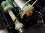
2. The below picture shows the wiring from the board to the back and front part of the car and also to the antenna. I'm bit lost in the antenna part, as can be seen in the picture the antenna goes to a coil form and a yellow wire is soldered near the screw, how does this work ?

3. The below picture shows the front part of the car that is wired from the board to a magnetic kind of thing which are 'hooked' into the axle of the wheel so it can move left and right I was wondering how does the board sends 'signal' to the magnet so that it turn clockwise of anti-clockwise so as to make the axle turn ?

4. Last picture that I need to clarify is the back of the car the wire from the board runs through to a 'motor' kind of thing which in turn will turn the wheel but confuses me is there is a capacitor soldered near the motor, can anybody tell me why is this done like this and what is the function ?


That's all for now, and thanks for your help.
Sorry if I'm posting in the wrong thread and feel free to move my post to the appropriate thread.
I'm trying to learn more about electronics and also about microprocessor so I thought the best way is to rip out an old RC car, hope the good people in this forum can help me to understand better what I'm looking at. I've taken few picture of the RC car and would like some guidance on few things I'm trying to understand:
1. The below picture shows what the main board of the car looks like there is small microprocessor (not sure what kind it is), was wondering if anybody know whether this is PIC or some kind of processor ? besides the processor I'm bit confused why there are so many resistors, capacitors ?
2. The below picture shows the wiring from the board to the back and front part of the car and also to the antenna. I'm bit lost in the antenna part, as can be seen in the picture the antenna goes to a coil form and a yellow wire is soldered near the screw, how does this work ?
3. The below picture shows the front part of the car that is wired from the board to a magnetic kind of thing which are 'hooked' into the axle of the wheel so it can move left and right I was wondering how does the board sends 'signal' to the magnet so that it turn clockwise of anti-clockwise so as to make the axle turn ?
4. Last picture that I need to clarify is the back of the car the wire from the board runs through to a 'motor' kind of thing which in turn will turn the wheel but confuses me is there is a capacitor soldered near the motor, can anybody tell me why is this done like this and what is the function ?
That's all for now, and thanks for your help.