Continue to Site

Welcome to EDAboard.com

Welcome to our site! EDAboard.com is an international Electronics Discussion Forum focused on EDA software, circuits, schematics, books, theory, papers, asic, pld, 8051, DSP, Network, RF, Analog Design, PCB, Service Manuals... and a whole lot more! To participate you need to register. Registration is free. Click here to register now.

Help with IGBT common ground circuit

Status
Not open for further replies.

oneprint

Newbie level 4
Joined
Oct 2, 2011
Messages
5
Helped
0
Reputation
0
Reaction score
0
Trophy points
1,281
Activity points
1,324
hi everybody,

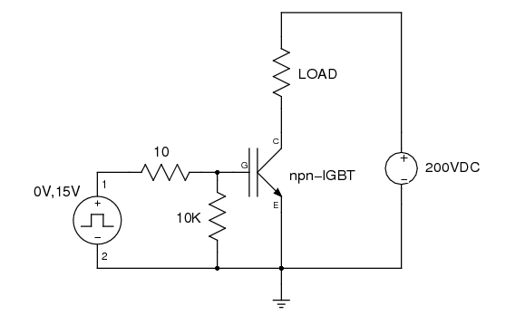
i have a problem that i need some help with. i basically have a switching circuit which uses a 555 to switch an IGBT. this circuit is run using 18vdc. the IGBT switches a circuit that uses about 200vdc.

the problem i have is that the IGBT has to be ground on both circuits in order for it to work. that is the IGBT emitter is ground on both high and low voltage circuits.

I have not yet tested the high voltage side of the circuit. i did test with 23vdc as a substitute for the high voltage side of the circuit and everything works fine.

Can some one tell me if its ok to ground both circuits together i would have thought the low voltage power supply would be exposed to the 200vdc and that sounds dangerous!

can some tell me how to isolate the low voltage side of the circuit. I know about optocouplers but i dont realy want to use them. also both circuits are battery powered.

I hope some one can help. thanks in advance.
:smile:
 

I think some more information is needed in order to give you some help. Are you using both IGBTs in a half-bridge or full bridge topology ? If so, the lower IGBT can use the common ground, but the upper one needs a "floating ground", by using a driver like an A3120/A2211 or a half-bridge driver like the IR2110.

Another thing: you can use optocouplers with battery, all you need is a dc-dc isolated converter, like a NME1215 or similar (this ones accepts 12V and delivers 15 volts).

Good luck with your project.

hi sergio, basically i am using the schematic below,


my problem is the low voltage signal circuit and the high voltage power circuit sharing the same ground. will not the amperage
from the high voltage circuit feed into the low voltage power supply? i dont realy want to make the circuit any more complicted. The 555 timer
drive the IGBT fine. i just want to isolate the low voltage signal circuit ground from the high voltage circuit. i hope you understand what i mean.

thanks for your help!!
 

If both sources are from batteries, then their shouldn't be a problem. Simply sharing one common node won't allow current from the high voltage supply to flow to the low voltage side. Current needs a complete loop to flow.

If you want isolation then you'll need something like an optocoupler with its own isolated supply (which will then need to be common to the HV supply). Or use a gate drive transformer, but that's not always applicable, especially if you want duty cycle over 50%.

hi, thanks for the reply. well the timer circuit is powered by 18v batteries and the high voltage is by means of an inverter which outputs 240 vac that is recified to
about 300 vdc. both circuits share a common ground as mentioned.

will that work ok?
 

Status
Not open for further replies.

Similar threads

Part and Inventory Search

Welcome to EDABoard.com

Sponsor

Back
Top