Continue to Site

Welcome to EDAboard.com

Welcome to our site! EDAboard.com is an international Electronics Discussion Forum focused on EDA software, circuits, schematics, books, theory, papers, asic, pld, 8051, DSP, Network, RF, Analog Design, PCB, Service Manuals... and a whole lot more! To participate you need to register. Registration is free. Click here to register now.

How to smoothly switch active between constant I and constant V?

Status
Not open for further replies.

uoficowboy

Full Member level 3
Joined
Apr 4, 2009
Messages
169
Helped
6
Reputation
12
Reaction score
5
Trophy points
1,298
Location
Seattle, Wa, USA
Activity points
2,964
Hi - I'm working on a active load that will be used for battery testing (among other things). A standard means of discharging a battery is the constant current, constant voltage discharge. This means, say with a li-ion, begin by discharging a full cell at a constant current. Once the voltage of the cell hits a minimum voltage you switch to constant voltage and let the current taper off till a set amount.

My plan is for my load element to be a FET on a large heatsink. A microcontroller controlling a DAC that also has various IOs available will be controlling everything. I could have two DACs if needs be.

I can easily design a DAC controlled constant current or constant voltage load. But I don't know how to make a system that can transition between the two. Any suggestions?
 

Imagine a PI controller and two error signals (voltage and current) that are combined by a max() respectively min() function.
 

Imagine a PI controller and two error signals (voltage and current) that are combined by a max() respectively min() function.
Are you talking about implementing a PI controller in software or in hardware?

In hardware I am having a lot of difficulty imagining how I can create my error signal. I mean at times I want my error signal to be dependent on I, other times dependent on V. I don't think I ever really want it dependent on both.

Any suggestions? I just can't quite figure it out...
 

Are you talking about implementing a PI controller in software or in hardware?
I understood your question related to analog hardware, but the solution applies to both.
In hardware I am having a lot of difficulty imagining how I can create my error signal.
Why? Lack of imagination? Error signal is the difference between setpoint and process value, in soft- and hardware controller as well. A max() or min() function can be basically implemented by two diodes. Perhaps you should look out for existing constant V/constant I examples. Take e.g. a look at the TL494 datasheet, how the device combines two error signals.
 

Why? Lack of imagination? Error signal is the difference between setpoint and process value, in soft- and hardware controller as well. A max() or min() function can be basically implemented by two diodes. Perhaps you should look out for existing constant V/constant I examples. Take e.g. a look at the TL494 datasheet, how the device combines two error signals.
FvM - sorry for the slow response. How would I achieve a PI controller in hardware? I'm not familiar with a circuit that does this.

Thanks!
 

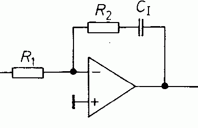
An inverting OP amplifier with RC series circuit in the feedback path has a PI characteristic.
 
One way to do it in hardware would be to build a constant current generator using your FET power transistor. So far so good. Now at your voltage setpoint, you have to divert the CC into a shunt circuit so its diverted from your battery. rather like a super zener diode, but adjustable.
Frank
 

An inverting OP amplifier with RC series circuit in the feedback path has a PI characteristic.

Sorry, but I'm afraid I don't understand. Could you draw a simple circuit that achieves this? Wouldn't the inverting OA have zero DC response then?
 

30_1301096304.gif
 
Status
Not open for further replies.

Part and Inventory Search

Welcome to EDABoard.com

Sponsor

Back
Top