Continue to Site

Welcome to EDAboard.com

Welcome to our site! EDAboard.com is an international Electronics Discussion Forum focused on EDA software, circuits, schematics, books, theory, papers, asic, pld, 8051, DSP, Network, RF, Analog Design, PCB, Service Manuals... and a whole lot more! To participate you need to register. Registration is free. Click here to register now.

Power Amplifier Bypass capacitors

Status
Not open for further replies.

elektr0

Full Member level 5
Joined
May 2, 2006
Messages
279
Helped
2
Reputation
4
Reaction score
3
Trophy points
1,298
Activity points
3,374
Hallo,

i am still wondering if the VDD drain supply bypass capacitors of our microwave amplifiers (Hittite HMC562) should be able to short-circuit the RF signal (2-35GHz).
This would mean the bypass C is a microwave component as well.
So, can we use simple DC SMD capacitors ?

93_1268066243.jpg


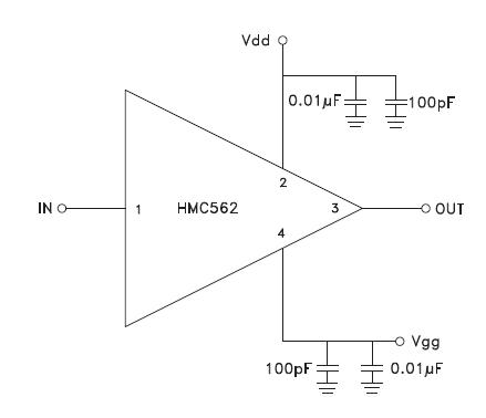
https://www.hittite.com/content/documents/data_sheet/hmc562.pdf

Thank you for your help.

elektr0
 

yes and no. SOME standard low frequency capacitors will work at very high frequencies, others will not. A lot depends on what the electrode structure inside the capacitor is like. Also, you have to place those parts very close to the amplifier and have low inductance multiple vias to a good ground plane. You want to pick one your company uses a lot, measure it, and if it is good, make sure nobody substitutes another manufacturer's part number for it. It also helps if you have multiple caps of different value, so if there is a resonance, it is somewhat dampened by the component next to it.

Also, of course, you would want a bigger cap somewhere in the circuit, such as a 10 uF, espcecially if you are carying complex modulation on the amplifier.
 

Yes,
As biff44 told, + select for 100pf/1nF so called HF capacitors/or porcelan Cs; most knowed vendor is maybe ATC, but up to 1nF/10nF NPO/COG, over their minimum X7R series, not Y5U/V...
K.
 

since 35GHz is quite high you may want to add a 10pF microwave bypass cap as well.
 

Hallo,

thanks for your reply.
So, we try to completely reflect the RF power arising at the VDD port.
What S21 values are preferred, if Iperform S-Parameter S-Parameter Simulations
(50 Ohm at VDD and 50 Ohm at Supply_Output!!!) on shunt-C's from Murata
GRM188, GRM155, GRM033.
Many Cs in parallel with different Series Resonant Frequencies will produce frequency areas with very low impedance and spikes inbetween with significant transmission from VDD to supply_output.

Added after 1 hours 4 minutes:

@mfding:
Below, you see the rejection and transmission of a murata 0402 10pF capacitor GRM155.

Self Resonance @ 2GHz, nearly no rejection / high transmission up to 20GHz.


Look this **broken link removed**
and this **broken link removed**
and this **broken link removed** ( price of this one you can see here **broken link removed** )
 

elektr0 said:
Hallo,

thanks for your reply.
So, we try to completely reflect the RF power arising at the VDD port.
What S21 values are preferred, if Iperform S-Parameter S-Parameter Simulations
(50 Ohm at VDD and 50 Ohm at Supply_Output!!!) on shunt-C's from Murata
GRM188, GRM155, GRM033.
Many Cs in parallel with different Series Resonant Frequencies will produce frequency areas with very low impedance and spikes inbetween with significant transmission from VDD to supply_output.

Added after 1 hours 4 minutes:

@mfding:
Below, you see the rejection and transmission of a murata 0402 10pF capacitor GRM155.

Self Resonance @ 2GHz, nearly no rejection / high transmission up to 20GHz.


these sparked spots are due to resonance which is inevitable due to parasitic inductor of the capacitor. therefore beyond the resonant frequency the capacitor acts as a inductor (which not what you want normally). larger capacitor typically have lower resonant frequency (which means the useful range the cap covers is lower). if a 10pF cap resonates at around 2-3GHz then the 100pF probably resonates at several hundreds of MHz. adding the 10pF cap could thus improves the range of frequency it covers (upto a little beyond its resonant frequency). if this is not enough then you may need add even lower values caps (e.g. 1pF) or you could pick up good chip caps with higher resonant frequency (such as the ones suggested by ledum, but of course they are also much more expensive). of course, if you are not worried about those high frequencies (beyond 1GHz) then you dont have to use cap smaller than 100pF.
 

Tnx!
Very nice products_they are new for me:)...
K.
 

Actually, the "spikes" are caused by something called Foster's Reactance Theorem. It states that the reactance increases with frequency. So if you have one capacitor that is a good short circuit at say 10 Ghz, but then gets inductive/lossy above that...if you have another capacitor that is a good short circuit from 15 Ghz to 40 GHz in parallel...somewhere between where the low frequency cap pooped out and the higher frequency cap took over there has to be a point where the total impedance passed thru an open circuit. It might have passed thru it very quickly with frequency, but it has to go thru it. You just hope that the capacitors are a little lossy so that they do not form a really good high Q open circuit, and you hope that your amp chip is happy with weird impedances at the dc lines for those brief points.

(note, foster's reactance theorem has been a little watered down recently by the use of metamaterials! In fact, I wonder if the ultimate solution to such bias line resonances does not involve metamaterials?)
 

Status
Not open for further replies.

Part and Inventory Search

Welcome to EDABoard.com

Sponsor

Back
Top