trastikata
Member level 1
Hello,
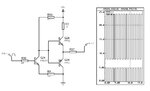
I am trying to figure it out why the following circuit is not working properly in reality while in theory should work. It is a P-CHANNEL FET driver shifting the gate voltage within the limits of the MOSFET.
The input (R39) is a 5v control signal and in my simulation at R37 it should swing between 8v and 24v. However when I built the circuit, the voltage changed only between 9v and 10 volts (the MOSFET after R37 is removed). When the TIP122 and TIP127 are removed, voltages at the 2N2222A are correct, but when I place the TIP122 and TIP127 the output is only between 9 and 10v.
I replaced all transistors with new ones and still got the same problem. Any help what am I missing and where could be/is the problem?
Thank you.