Continue to Site
Follow along with the video below to see how to install our site as a web app on your home screen.
Note: This feature may not be available in some browsers.
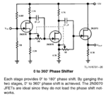
It will work but the limitations of the components, particularly the potentiometer will seriously degrade it as the frequency increases. The principle is to use the first and second stages as phase splitters, the drain and source signals will be (theoretically) inverted. One is then fed through a capacitor to provide fixed further shift and the other through a variable path, the variable resistance. The point where they meet will sum a waveform from the difference of the signals. The main complication is the poor passage of HF through the potentiometer into the load capacitance. You probably need to scale the coupling capacitor down to a much lower value, maybe a few 10's of pF and the potentiometer down to 1K or less to make it effective. It will also null the frequency when R=XC so expect the output level to be very variable as the control is turned.
The circuit will work best at low frequencies and is often used to produce 'hollow' or spacial sound effects in music. For RF it will still work but not very well.
Brian.
adjust both LOparts to be of equal amplitude.
3. Since only 90 degrees of difference are needed, I could probably remove the second stage?
By adding an inductor to the capacitor, attenuation is not as severe. Because you don't have a resistor involved. For 1-30 MHz range an inductor consists of a few turns around a pencil.
A tunable inductor and/or capacitor could make things simpler.
There is more than one way to arrange the LC network (depending on whether you want phase advance or delay), and a potentiometer is still an option. It requires experimentation with a few configurations.
The all-pass circuit implemented in post #1 does ideally not involve magnitude variations, as longs as R >> Rs, Rd.
You mean replacing the resistor with an inductor and the capavitor with a variable one?

It's an idea worth some experimentation.
Or to have a potentiometer choose how much comes from a capacitor and how much from an inductor.
This simulation selects a range between phase advance or retard.
The potentiometer was dialed from left to right during the run. The scope trace tells the story. Notice at the beginning, output phase leads the source. By the end, output lags.
View attachment 155050
These values seemed suitable for 5 MHz. They were chosen to attenuate the source 5V amplitude about half. To select values your own project 1-30 MHz may require some trade-offs in performance.
There is another possibility: make a series LC. Ground one end, apply your signal to the other end. Tap for output between the L & C.
Reverse the LC, to obtain different behavior.
The phase shift in your original post depends on the reactance of the capacitor so it varies with frequency. If you manage to find suitable values it will still need 'tuning' to each frequency to get the required shift. Note that AGC will help to stabilize the output level but there is theoretical zero in the output when the resistor is adjusted to some point and you won't be able to compensate for that.
Brian.