Continue to Site

Welcome to EDAboard.com

Welcome to our site! EDAboard.com is an international Electronics Discussion Forum focused on EDA software, circuits, schematics, books, theory, papers, asic, pld, 8051, DSP, Network, RF, Analog Design, PCB, Service Manuals... and a whole lot more! To participate you need to register. Registration is free. Click here to register now.

How to design higher order bandpass filter using only L,R,C?

Status
Not open for further replies.

wajahat

Advanced Member level 4
Joined
Feb 3, 2006
Messages
102
Helped
3
Reputation
6
Reaction score
1
Trophy points
1,298
Activity points
2,097
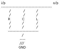
hi ,i am new to filter designing and want to know how can i design higher order bandpass filter using only L,R,C components.I don't want to use any active components.e.g. amplifier.
Any relevant material in this regard would be helpful.
Thanks.
Wajhat.
 

Re: How to design higher order bandpass filter using only L,

**broken link removed** is a free design program. This will get you by for the moment, but you should read some books on passive filters to gain knowledge and talent in passive filters.
 

You can quickly design passive filters using MicroCap 7.1.6 or later:

Design -> Passive Filters -> chouse bandpass -> enter Center freq., passband, slopband and type (Chebyshev or Butterworth)
 

    wajahat

    Points: 2
    Helpful Answer Positive Rating
Re: How to design higher order bandpass filter using only L,

Filter order and type is solely defined by the poles and zero's of the transfer function of the filter. Chebyshev, Butterworth, Bessel, etc. refer to the types of polynomials that are used to define the filter response.

This is separate from the implementation, which could be with an active device, LC Ladder, coupled resonators, etc.

Dave
www.keystoneradio.com
 

Re: How to design higher order bandpass filter using only L,

the circuit is very simple, that is by putting R in parallel with (C parallel to L):

47_1167471549.JPG


Fc=1/sqrt(LC)
and the band pass width will be determined by the quality factor of the resonance circuit "Q" which is fn(R)

But this will give you a low order BP filter..

for higher orders without any active elements, I suggest to use more similar stages in cascade....

Thanks
 

Re: How to design higher order bandpass filter using only L,

Enhancer said:
the circuit is very simple, that is by putting R in parallel with (C parallel to L):

47_1167471549.JPG


Fc=1/sqrt(LC)
and the band pass width will be determined by the quality factor of the resonance circuit "Q" which is fn(R)

But this will give you a low order BP filter..

for higher orders without any active elements, I suggest to use more similar stages in cascade....

Thanks


Impedance in and out-port is also including in above fn(R) case

You can try itsef on Vipec

https://downloads.sourceforge.net/vipec/ViPEC-3.1.3.zip?modtime=1034467200&big_mirror=0

After install (open only a new file map and put in files from archive), starting Vipec and under 'ckt'-map, open 'bandpass.ckt', put a 'cassette player button' and new diagram shows up (but stacked together), spead around diagrams and you se simular picture down here.

Most usable tools IMHO (under meny tools) is a 'tuner' ('circurit tuner' in picture) and on checked 'auto sweep', diagrams uppdate in real time same time you adjusting component values. Very useful for hands on tuning simular real life tuning and I miss this of most type of Spice-simulators.

For example tuning filters, you need play around some time and make 'feeling' how rule works before you can make good tunings - this is hard/impossible to make in spice-simulators... (theoretic people says I going wrong way, but I never seem theroretic filter implement to real life with 'two turn up, three down' in exact calculated schematic and measure step for step and take half a day to find out for just one uniqe unit, and 'simple filter guy' as me, fiddle it in few minutes and make better filter - and this fact drive theoretic guys to nut and screaming after 'how you do it, how you thinking, can you tell me alghoritm!"... - yes is a self experience on my work for couple yeras ago...)

Vipec is under open source (new version only under linux, but stand still just now...) and if you feel missing function - you is free to improve programs ;-)

---

I try quite complex problem as matching crystal filters in high Ohm enviroment in this program with couple of measured S-parameter block from VNA, and done as well as multi tentousendollars Ansoft programs etc.

I measure crystall itself, driver side, load side in smallest piece as possible.

Crytal filter itself like a hell and very bad shape in 50 Ohm measure enviroment as VNA, but on right (complex) impedans enviroment in simulator is going nice shape..., take values (for example source and load impedance) and place value on real equipment and you see after little tuning same good shape - is was impressive I make it first time :)
 
Last edited by a moderator:

Re: How to design higher order bandpass filter using only L,

If possible, get a copy of Zerev's "Handbook of Filter Synthesis"
 

Status
Not open for further replies.

Similar threads

Part and Inventory Search

Welcome to EDABoard.com

Sponsor

Back
Top