Continue to Site

Welcome to EDAboard.com

Welcome to our site! EDAboard.com is an international Electronics Discussion Forum focused on EDA software, circuits, schematics, books, theory, papers, asic, pld, 8051, DSP, Network, RF, Analog Design, PCB, Service Manuals... and a whole lot more! To participate you need to register. Registration is free. Click here to register now.

Implementing an 8-bit carry lookahead adder in cmosp18 technology

Status
Not open for further replies.

Crusader370

Junior Member level 1
Joined
Jun 19, 2006
Messages
17
Helped
0
Reputation
0
Reaction score
0
Trophy points
1,281
Location
montreal, canada
Activity points
1,425
Hi All,

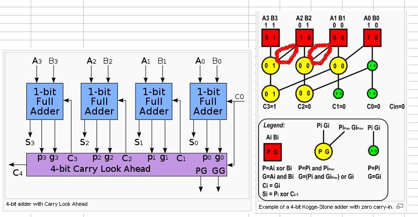
We have a project to implement an 8-bit carry lookahead adder in cmosp18 technology. Do you have any suggestions on what type of logic to use? At the moment, we are thinking of implementing a logarithmic adder (Kogge-Stone) in static CMOS, but one thing that we noticed is that we have way too many inverters in our critical, and other, paths.

Do you have any suggestions for us? Did we choose the right path?

Thanks,

Crusader

P.S. Oh yes, and the criteria is that it is supposed to be as fast as possible.
 

8 bit static manchester carry chain adder

why don't you use the Manchester carry chain??
 

8 bit manchester carry chain adder critical path

there are few ieee papers on implementation of high speed adders with different technology. refer those if possible
 

manchester 8 bit adder

Do you know of a typical speed of the adder? Our worst-case delay is 1.15ns at the moment...
 

8-bit adder

it is depend on how many bits does your addr have. i have a adder, which is 16-bit CLA. its worst-case delay is nearly 1.03 ns.
 

Re: 8-bit adder

among tree adders, kogge-stone is the fastest since it requires fewest number of series logic levels (4 levels for 16bit addition actually); however, that requires a good deal of hardware (in parallel) and dense wiring. brent-kung requires 7 series logic levels, hence it is apperently slower than kogge-stone, but requires very few hardware and wiring. there are hybrid versions like knowles.

i have built 16bit kogge-stone adder recently (though i didnt optimize the critical path) and it has a 2nanosecond delay, in an enviroment where an inverter chain has a delay of 0.1nanosecond per stage..

tree adders are preferred when the number of bits to add is higher than 8.
so in your case, you should look for other adding schemes, like maybe 2 manchester carry chains in series, since it might be better than a 3 stage kogge-stone adder.
 

Re: 8-bit adder

How do you measure the worst case delay?

I think it is when you add 11111111 + 100000001 = 1 10000000

The simulations definitely seem to confirm that... but I might be mistaken.

Again, we are using the Kogge-Stone 8-bit adder (too late to change it now). Oh yeah, there is no Cin.

The worst case 50% input to 50% ouput propagation delay is 0.59ns.
 

8-bit adder

i measure my adder's worst case delay by tools, such as PT or DC.
 

Re: 4-bit adder using kogge-stone

hello guys can you share references on how to implement kogge-stone?
 

Re: 8-bit adder

https://www.cmosvlsi.com/coursematerials.html
lecture 11 talks about Adders.

below is the verilog code ( verified with Verplex/Conformal LEC) of 8bit Kogge-stone adder.

=================================

Code Verilog - [expand]
1
2
3
4
5
6
7
8
9
10
11
12
13
14
15
16
17
18
19
20
21
22
23
24
25
26
27
28
29
30
31
32
33
module add(sum,cout,a,b,cin);
input [7:0] a,b;
output [7:0] sum;
input cin;
output cout;
 
// input stage
wire [7:0] g,p;
assign g = a & b;
assign p = a ^ b;
 
//LAC tree
wire [7:0] G1,P1,G2,P2,G3,P3;
wire [7:0] c;
gp #(8) gp1( g[7:0], p[7:0],{ g[6:0],cin},{ p[6:0],1'b1},G1[7:0],P1[7:0]);
gp #(7) gp2(G1[7:1],P1[7:1],{G1[5:0],cin},{P1[5:0],1'b1},G2[7:1],P2[7:1]);
gp #(5) gp3(G2[7:3],P2[7:3],{G2[3:0],cin},{P2[3:0],1'b1},G3[7:3],P3[7:3]);
assign G2[0] = G1[0]    ;assign P2[0] = P1[0];
assign G3[2:0] = G2[2:0];assign P3[2:0] = P2[2:0];
assign c[7:0] = {G3[6:0],cin};
 
// output stage
assign sum = p ^ c;
assign cout = g[7] | p[7]&c[7];
endmodule
 
module gp(g2,p2,g1,p1,g,p);
parameter size = 1;
input  [size-1:0] g1,p1,g2,p2;
output [size-1:0] g,p;
assign g = g2 | g1&p2;
assign p = p1&p2;
endmodule


=================================
 

Re: 8-bit adder

hi koggestone, i see the site but "kogge stone implementation was not explain..do you know where i can see more of it on how it was done and was implemented?
 

Re: 8-bit adder

laiza said:
hi koggestone, i see the site but "kogge stone implementation was not explain..do you know where i can see more of it on how it was done and was implemented?

The above verilog code i gave , is more "structural" and shows how koggestone adder is implemented.

My advice is take a paper and pencil and draw 5 rows and 8 columns (for a 8 bit adder) , where 1 row is input generation , 1 row for output generation , 3 rows ( log2(8) = 3 ) are for carry tree. then connect these instances as shown in verilog code.

look at this wiki page to see how it looks once u connect them
https://en.wikipedia.org/wiki/Kogge-Stone_adder

google the phrase "kooge stone adder" for more detailed info . ( since this adder was published in 1973 , there should be many slides/papers available on web).
 

Re: 8-bit adder

Hello need your subject matter expertise regarding the block diagram below.

How will the connection marked in red connected in the adder circuit.
Appreciate it very much.


Re: 8-bit adder

Yes!..Already done the implementation of this design. I wonder any materials that would discuss where and when to use this implementation...References are scarce for this topic...:(
 

Re: 8-bit adder

refer to this might be of some help

**broken link removed**
 

Status
Not open for further replies.

Part and Inventory Search

Welcome to EDABoard.com

Sponsor

Back
Top