Continue to Site

Welcome to EDAboard.com

Welcome to our site! EDAboard.com is an international Electronics Discussion Forum focused on EDA software, circuits, schematics, books, theory, papers, asic, pld, 8051, DSP, Network, RF, Analog Design, PCB, Service Manuals... and a whole lot more! To participate you need to register. Registration is free. Click here to register now.

Circuit don't work in Microcap (555-based class-D)

Status
Not open for further replies.

nast

Newbie level 2
Joined
May 22, 2020
Messages
2
Helped
0
Reputation
0
Reaction score
0
Trophy points
1
Activity points
26
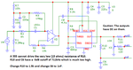
Hello Maybe someone has simple (the simpler the better) circuit for a low-frequency transistor amplifier with a class D cascade, or can explain how to creat it, I'm going to make it in Microcap? I can only find very complex circuits in internet.
 

Re: Class D amplifier circuit how to make

Run a 555 timer IC to generate a pulse train.
Apply varying voltage to pin 5. This alters duty cycle.
It's the makings of a class D amplifier.

555 is class D amplifier LC 2nd-order fil 60 ohm load gets 3V sines.png

The LC network acts as a low-pass filter, second order. Its values need to be customized to the load and frequency.

A load should always be connected so that the LC network does not start oscillating at its resonant frequency to an extent that becomes destructive.
 
  • Like
Reactions: nast

    nast

    Points: 2
    Helpful Answer Positive Rating
Don't expect particularly good results from that circuit. In astable mode the control pin can change the frequency as much as the pulse width and the output is not AC coupled so it shouldn't be used directly to drive a loudspeaker or headphones.

You will get better results if you trigger the 555 from an external fixed frequency and wire it in monostable mode. The 'out' connection should be connected to the load through a capacitor to remove the DC offset.

Brian.
 

Hi,

... or use a ready to buy class D amplifier IC.

Farnell lists about 30 different ICs below 1€. And they have good audio quality and power.


Klaus
 

I cropped your schematic so it looks almost as clear as the original. I do not know why you changed all the R and C numbers.
I think an old 555 timer makes a very poor class-D amplifier.
 

Attachments

  • class-D headphones amp.png
    class-D headphones amp.png
    48.6 KB · Views: 216

The principle is to vary duty cycle of pulses (PWM) depending on voltage of input signal.

Here is a class D amplifier, starting with a triangle wave generator (found in the Circuits menu of Falstad's simulator).

Experiment until we discover which is a strategic spot where we can influence the triangle waves. Apply the incoming signal.
Feed the output to a logic gate.

class D amplifier 2 op amps triangle wave sine input output 5V PWM.png

Notice the carrier frequency itself does not change.
 

Simpler yet. Start with an ordinary relaxation oscillator built from a single op amp. (Normal output is AC square wave.)

Turn it into a class D amplifier by applying signal at strategic location.

class D amplifier 1 opamp 1kHz sine input output 5V PWM.png

I tried this in hardware and it works.
 

Status
Not open for further replies.

Part and Inventory Search

Welcome to EDABoard.com

Sponsor

Back
Top