Continue to Site

Welcome to EDAboard.com

Welcome to our site! EDAboard.com is an international Electronics Discussion Forum focused on EDA software, circuits, schematics, books, theory, papers, asic, pld, 8051, DSP, Network, RF, Analog Design, PCB, Service Manuals... and a whole lot more! To participate you need to register. Registration is free. Click here to register now.

3kW DC-DC Converter Design Guidance

Status
Not open for further replies.

ku637

Advanced Member level 4
Joined
Apr 6, 2011
Messages
116
Helped
2
Reputation
4
Reaction score
3
Trophy points
1,298
Activity points
2,551
Hello,

I want to explore the possibility of an isolated low-cost 3kW DC/DC (automotive purpose), VIN 220-470VDC ,VOUT~14V , efficiency expectation is ~95% peak.

Im more concerned about cost here, so can anyone suggest me the right approach to such a target?

Preferred topology PSFB or LLC?, devices selection- Si, SiC, GaN, Transformer- Planar or other?

Any suggestion will be really helpful.

Thanks
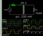
 

Best efficiency means current is always flowing. As in a transformer carrying bipolar AC.

Full H-bridge is typical. To make things simple this simulation applies square waves. 330V is in the middle of your supply range. (I'm guessing that 500 Hz is a reasonable switching frequency.)

xfmr step-down 330VAC sq wave to 15VAC load 3kW 500Hz.png

The 1 ohm resistor represents parasitic losses, 100W, although you can expect greater losses.

The secondary side must carry 200 Amperes. About the size of the cable going to a car's starter.


Hello,

I want to explore the possibility of an isolated low-cost 3kW DC/DC (automotive purpose), VIN 220-470VDC ,VOUT~14V , efficiency expectation is ~95% peak.

Im more concerned about cost here, so can anyone suggest me the right approach to such a target?

Preferred topology PSFB or LLC?, devices selection- Si, SiC, GaN, Transformer- Planar or other?

Any suggestion will be really helpful.

Thanks

You can go with PSFB with current doubler with synchronous rectification on secondary side. As the output current is very high(around 214A). Consider using 2 PSFB in parallel in order to avoid a big transformer & improve the overall efficiency. You can also use them in master & slave configuration. There are also some ICs like UCC28950 (Texas Instruments)which has synchronization feature wherein you can eliminate output ripple voltage & lower EMI in more than one phases.

If cost is the concern ,don't go ahead with SiC or GaN devices...You can go ahead with Si Super junction Mosfets(For Bridge) from Onsemi. They are cheaper compared to other manufacturer.

Secondary side mosfets(for synchronous rectificatio) must have very low Rds On(Put atleast 2-3 in parallel)

Again with planar for transformer will be a costlier option. PQ cores will be a better option for reducing the EMI...
 
Last edited:

Status
Not open for further replies.

Similar threads

Part and Inventory Search

Welcome to EDABoard.com

Sponsor

Back
Top