Umamaheswar
Newbie level 4
Hello everyone,
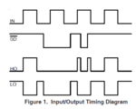
I given the complementary pulse(one is high one is low opposite) to the IR2109s driver, when am testing with that, the input side is showing the complementary pule and the output side is coming both are high pulse not complementary. can anyone tell me the region why it is coming like that but i want complementary pulse on output side. I given the voltage to driver 15V DC and 24v DC.
I given the complementary pulse(one is high one is low opposite) to the IR2109s driver, when am testing with that, the input side is showing the complementary pule and the output side is coming both are high pulse not complementary. can anyone tell me the region why it is coming like that but i want complementary pulse on output side. I given the voltage to driver 15V DC and 24v DC.
