- Joined
- Jul 4, 2009
- Messages
- 16,255
- Helped
- 5,140
- Reputation
- 10,309
- Reaction score
- 5,123
- Trophy points
- 1,393
- Location
- Aberdyfi, West Wales, UK
- Activity points
- 137,572
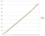
I've been developing a product that utilizes the ADC inputs of a WROOM-32D module and found some quite alarming anomalies. The linearity seems to be horrible. To check, I've done this:
1. stepped the input voltage up in 100mV increments between 0V and 3.3V. The source is accurate to +/- 1mV.
2. used a low impedance voltage source (<10K).
3. used a stable 3.3V supply voltage.
4. Taken the average of 10 readings at 1 second intervals.
I'm seeing a dead zone below about 0.15V input and an FSD reading above 3.1V, possibly indicating it has an internal amplifier that can't manage rail-to-rail . Reading up on various internet articles I can see others are noticing this too. For my application, the input will typically be between 0.3V and about 2.0V so the extremes are not too important. For the range I'm interested in I can 'straighten' the non-linearity sufficiently by multiplying the ADC reading by 0.96 then adding a small constant. However, that is on the module used for development, when I repeated the tests on a different WROOM-32D, the results were wildly out. I plotted the readings for both modules on a graph and although they follow the same general shape, the lines were significantly (>5%) different.
Has anyone else used these modules and noticed the same problem? Maybe found a work-around? It is the difference in modules that concerns me most, I don't want to go into a lengthy calibration process on each one.
Brian.