Continue to Site

Welcome to EDAboard.com

Welcome to our site! EDAboard.com is an international Electronics Discussion Forum focused on EDA software, circuits, schematics, books, theory, papers, asic, pld, 8051, DSP, Network, RF, Analog Design, PCB, Service Manuals... and a whole lot more! To participate you need to register. Registration is free. Click here to register now.

High Input Current DC-DC Converter?

Status
Not open for further replies.

emaq

Member level 4
Joined
Sep 17, 2015
Messages
78
Helped
0
Reputation
0
Reaction score
1
Trophy points
1,288
Activity points
2,001
I am looking for a DC-DC converter design with the following specifications.

Vin = 24 V
Iin = 135 A

Vout = 60 V
Iout = 50 A

Which topology will work in this case? Any design or schematic?
 

If isolation required, LLC converter, otherwise multiphase synchronous boost.
 

current fed push pull is a good option too at low vin - keeps the current in the devices to low levels - splitting into 2 converters will assist greatly too ...

- - - Updated - - -

also - for non-isolated two interleaved boosters will work very nicely ...
 

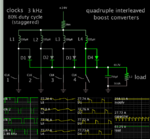
To follow up on the above suggestions, here's a simulation of quadruple interleaved boost converter. 24V supply stepped up to 60V 50A.

quadruple boost converter clk-driv 24V supply load gets 60V 50A.png

As you can see it requires much greater supply current than your spec 135 A.

It's important to reduce all parasitic resistance.
 

respectfully, the 26 milli-ohm res has 474 watts for 135 amps only, each of the diodes has 8 watts for every 10 amps thru - so the losses mount up for non ideal components

- - - Updated - - -

the numbers given at top imply a 92.5% eff which should be possible with synch rect boost diodes/fets - splitting into 4 phase shifted units of 34 amps each - ave ...

- - - Updated - - -

[ the 26 milli-ohms shown actually drops the Vin by 6.7V and consumes 1730 watts dropping the eff to 50% - better to have 4 x 0.026 ohm R's I'm thinking ]
 
the numbers given at top imply a 92.5% eff which should be possible with synch rect boost diodes/fets - splitting into 4 phase shifted units of 34 amps each - ave ...

You are correct. Synchronous type is more efficient and was the type recommended above. I kept my simulation simple by making it asynchronous, with diodes.
 

The only way to properly decide, is to delve into app notes and data sheets from major semiconductor manufacturers.
Lots of reading, my friend.

When you find something similar to what you are looking for, these manufacturers will always include powerful simulation software and -for the real thing, demo boards you can perform real world experiments.

Both these tools allow you to experiment and modify the circuit, to meet your individual requirements.
You may find that certain parameters will be difficult to meet within the allowed budget constraints, and that is when the real fun begins :)
 

Status
Not open for further replies.

Similar threads

Part and Inventory Search

Welcome to EDABoard.com

Sponsor

Back
Top