student14
Member level 2
Hello
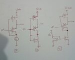
I want to know the difference of all three FVF in the attached diagram. The current source in Fig. a can be replaced by current mirror in Fig. C. This I can understand but what about Fig b. If the current source is is replaced by diode connected MOS. Is the diode connected MOS operated in triode region or saturation region? because mostly instead of current source a resistor can be placed for current to flow across resistor.
Can some one explain the differencein fig. b and fig. c?
