T
treez
Guest
Hello,
Does anyone have a schematic for this HSPY-400-01 Bench power supply? (400V, 1A)
**broken link removed**
Disassembled pics attached.
I have now been banned from tinkering further with it.
Ours blew up, and I took a look inside today, and indeed, it was the two switching FETs that had gone totally short from gate to drain to source. I took them out and was told to order new ones and then I was moved off this job. This is a shame as I was going to analyse this SMPS more.....may I ask if others have info on this power supply?, or any ideas, since I have been banned from further tinkering.
This PSU worked until two weeks ago, and I have never powered anything with it at more than 12 Watts
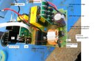
This PSU contains a top board which has a linear regulator output stage on it. A bottom board which has the offline isolated SMPS on it. Also a front board (which I haven’t unscrewed yet) and presumably this contains the microprocessors etc. There is also a little Fan PSU board. (This HSPY-400-01 PSU must have given its assemblers a few nervous breakdowns. I had to take 30 dis-assembly photographs.)
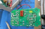
The offline SMPS bit seems unusual for a 400V, 1A PSU..... It has no PFC stage. Instead there is the AC filter, and then the rectifier bridge…then a 330uF, 400v electrolytic capacitor. Then there is the transformer isolated SMPS. This appears to be a half bridge LLC converter (but possibly a series resonant converter of course) . It does comprise a current transformer. It does appear to have rail splitting film capacitors (each 200nF) which are supposed to protect LLC converters from startup transient damage etc. The Resonant capacitor appears to be 1 inch long 6.8nF film capacitor.
The 68uF electrolytic output capacitor of the LLC converter is only 400V rated…and 400V is a bit tight for a 400v output PSU…the unit has a linear regulator output stage, so presumably the LLC SMPS is outputting a little more than 400V when the unit is outputting 400V.
The LLC converter ( I believe it is that, after my short allotted time with it) looks very sparse on componentry. (pic attached) I cannot see a controller chip for it…….other than a IR21531S chip on a little daughter board which is a “self oscillating half bridge driver”...
IR21531S datasheet
https://www.infineon.com/dgdl/Infin...N.pdf?fileId=5546d462533600a4015355c8d26316b3
This is a cause for some concern, since LLC converters have failure modes which really need either a custom microcontroller solution, or a custom LLC converter IC.
Please may I ask if anyone has a schematic for this PSU?. I believe its very common as its so cheap. I am beginning to suspect that its not very robust at all.
Can anyone confirm the topology?
Does anyone have a schematic for this HSPY-400-01 Bench power supply? (400V, 1A)
**broken link removed**
Disassembled pics attached.
I have now been banned from tinkering further with it.
Ours blew up, and I took a look inside today, and indeed, it was the two switching FETs that had gone totally short from gate to drain to source. I took them out and was told to order new ones and then I was moved off this job. This is a shame as I was going to analyse this SMPS more.....may I ask if others have info on this power supply?, or any ideas, since I have been banned from further tinkering.
This PSU worked until two weeks ago, and I have never powered anything with it at more than 12 Watts
This PSU contains a top board which has a linear regulator output stage on it. A bottom board which has the offline isolated SMPS on it. Also a front board (which I haven’t unscrewed yet) and presumably this contains the microprocessors etc. There is also a little Fan PSU board. (This HSPY-400-01 PSU must have given its assemblers a few nervous breakdowns. I had to take 30 dis-assembly photographs.)
The offline SMPS bit seems unusual for a 400V, 1A PSU..... It has no PFC stage. Instead there is the AC filter, and then the rectifier bridge…then a 330uF, 400v electrolytic capacitor. Then there is the transformer isolated SMPS. This appears to be a half bridge LLC converter (but possibly a series resonant converter of course) . It does comprise a current transformer. It does appear to have rail splitting film capacitors (each 200nF) which are supposed to protect LLC converters from startup transient damage etc. The Resonant capacitor appears to be 1 inch long 6.8nF film capacitor.
The 68uF electrolytic output capacitor of the LLC converter is only 400V rated…and 400V is a bit tight for a 400v output PSU…the unit has a linear regulator output stage, so presumably the LLC SMPS is outputting a little more than 400V when the unit is outputting 400V.
The LLC converter ( I believe it is that, after my short allotted time with it) looks very sparse on componentry. (pic attached) I cannot see a controller chip for it…….other than a IR21531S chip on a little daughter board which is a “self oscillating half bridge driver”...
IR21531S datasheet
https://www.infineon.com/dgdl/Infin...N.pdf?fileId=5546d462533600a4015355c8d26316b3
This is a cause for some concern, since LLC converters have failure modes which really need either a custom microcontroller solution, or a custom LLC converter IC.
Please may I ask if anyone has a schematic for this PSU?. I believe its very common as its so cheap. I am beginning to suspect that its not very robust at all.
Can anyone confirm the topology?
Attachments

Last edited by a moderator: