Continue to Site

Welcome to EDAboard.com

Welcome to our site! EDAboard.com is an international Electronics Discussion Forum focused on EDA software, circuits, schematics, books, theory, papers, asic, pld, 8051, DSP, Network, RF, Analog Design, PCB, Service Manuals... and a whole lot more! To participate you need to register. Registration is free. Click here to register now.

Capacitor Burning issue due to unusual reasons

Status
Not open for further replies.

Prabhakarankft

Member level 3
Joined
Jun 22, 2019
Messages
54
Helped
0
Reputation
0
Reaction score
4
Trophy points
8
Location
Chennai, India
Activity points
623
Hello Everyone! Greetings!
I am having one Small PCB Board which is used to actuate the solenoids.. We will install in a solenoid and too many solenoids will be used for our field application.
Circuit is very simple. We are getting power and signals from Ribbon cables and in a single ribbon cable we will connect 16 PCB boards one by one( daisy Chain- 74HC595 IC used)

Input voltage: 15VDC
Voltage regulator: 78M05(1A SMD regulator)
Logical IC : 74HC595D(Nexperia)
Current Driver: ULN2803FWG( Thosiba)

Problem:
Sometimes 10uF/25V capacitor is started to burn and creates big flame. We using this capacitor across the input power supply. Since We using 15VDC as power supply My component vendor suggested to buy TMK316BJ106KL part...
Make: Taio yuden from Germany.. We ran a test at my supplier office the capacitor is withstanding up to 28VDC. We have tested this for 25 minutes continuously..

Capacitor rated voltage is 25VDC.. Is this enough for our application? Or any other reverse voltage from solenoids disturbing the capacitor? Out of 1000 boards 100 boards getting the same issue
Can anyone tell me if there is any SMD capacitor comes with 10uF/35V rating.?? I have heard that increasing the rated voltage of capacitor will solve this issue..

As per the input voltage Rated voltage 25VDC is correct selection I think. Capacitor should be 1.5 times higher than the input voltage.. Correct me if I am Wrong.
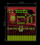
PCB Slave.PNG

Some people are saying this is due to Soldering issue?? Expecting good guidance
 

1.5 times the applied voltage is good but anything higher than supply should not burn out. I suspect the problem is due to the combined voltage of several solenoids switching off at once. The ULN2803 has diodes to conduct back-emf to the supply but with so many boards in a chain and fed through relatively high impedance cables it is quite likely the supply line carries a large spike of voltage as they turn off.

I don't think the rated voltage is the problem, I think you need to add a local (on each board) clamp to kill the spikes. I would suggest a Zener diode rated at say 18V across the 15V incoming supply. It will do nothing normally but will clamp any excess voltage.

Brian.
 

Hi,

This is no GND plane, thus you have increased serial impedance at every GND connection.
This is not reliable and thus not suitable for industrial design. --> use 2 layers PCB with one layer GND only ... and GND vias

But this will not cause the capacitor to explode.
A capacitor may fail, because of:
* high temperature (operating as well as soldering)
* high voltage (even peaks)
* high current ripple, depending on ripple frequency
* reverse voltage
* aging

We can not verify a single item, because we don't have the informations...

Klaus
 
1.5 times the applied voltage is good but anything higher than supply should not burn out. I suspect the problem is due to the combined voltage of several solenoids switching off at once. The ULN2803 has diodes to conduct back-emf to the supply but with so many boards in a chain and fed through relatively high impedance cables it is quite likely the supply line carries a large spike of voltage as they turn off.

I don't think the rated voltage is the problem, I think you need to add a local (on each board) clamp to kill the spikes. I would suggest a Zener diode rated at say 18V across the 15V incoming supply. It will do nothing normally but will clamp any excess voltage.

Brian.

Hello,
Really thanks for your best Technical support. I am having few questions to clarify

What you mean by "but anything higher than supply should not burn out".. Then what is the point of Rated voltage of any capacitors??

Does We need a Resistor before 18V Zener diode? If So 1206 resistor will be a good choice?? What would be the wattage of Zener ? It would be great if you refer Mouser or Element 14 Link or else part number?

Do we need any fuses to implement Zener? In case if Zener failes it will create short circuit right?? If So again We will have some other problems

Shall We use TVS diodes instead of Zener? I think TVS diode will give outstanding performance against Spikes!. Correct me if I am wrong..

We will check your suggestion and We will come back with results..
 

Hi,

This is no GND plane, thus you have increased serial impedance at every GND connection.
This is not reliable and thus not suitable for industrial design. --> use 2 layers PCB with one layer GND only ... and GND vias

But this will not cause the capacitor to explode.
A capacitor may fail, because of:
* high temperature (operating as well as soldering)
* high voltage (even peaks)
* high current ripple, depending on ripple frequency
* reverse voltage
* aging

We can not verify a single item, because we don't have the information...

Klaus

Hello Klaus! Thanks for your support! I could understand the difficulties of Single Layer PCB.. We will plan for 2 Layer as you stated.. I will give some extra information

*high temperature (operating as well as soldering)
Initially I have doubted on this. Later I have confirmed operating Temperature is nearly 32 Degrees a bit higher than room Temp..

* high voltage (even peaks)
There will be possibility for Higher voltage. Meanwell SMPS will take care of constant voltage output.. No chances for spikes from PSU

* high current ripple, depending on ripple frequency
As you know 74HC595 will consume less than 70mA current. Approximately total power consumption during the solenoid operation( Incl of solenoids) will be 200mA. Does this make any huge difference on capacitor operation. Ripples will burn out the cap??


* reverse voltage
I have no Idea about reverse voltage. So that I have some doubts on this. If I increase the

* aging
Since We using MLCC capacitor (tmk316bj106kl- 1206 Package 10uF/25VDC) there will be no aging effects.. It is applicable only for Electrolytic! Am I right?

Instead of SMD If We use 10uF/63V through hole capacitor what would be life cycle?? Device will be used 22 hours in a year? We should plan at least 7 years life right? How We can calculate life cycle of 10uF/63V Thr Cap?

Friends of mine suggesting me to use through hole capacitor Since it is easily available and voltage rating is nearly high.. If We increase the voltage rating means there will some chances to escape from capacitor burning issues
 

do the 16 solonoids have free wheeling diodes to handle the current at turn off?

Hello wwfeldman ! For your information I am using only 8 solenoids. You can see 16 points but 8 points used for Positive power for solenoids..

According to the datasheet of ULN2803 it is having in built Fly-wheeling diode. But I am sure it is enough for my application. Kindly guide me how We can confirm that??
 

A disadvantage of using a 25V capacitor is that it has only 30% of initial capacitance at 15V, see TMK316BJ106KL characteristic data. Use X5R/X7R capacitor below 50% of rated voltage as a rule of thumb. But no reason for damage though.

The 2803 circuit doesn't feed back any inductor fly-back current to the power supply, don't need to care about respective overvoltage.

Possible damage reasons that I would think of are:

- Capacitor cracked during assembly/handling. Is the board exposed to mechanical force, e.g. during separation of V-cut panels?

- Power supply is feeding large current surges, e.g. during power up.
 

What you mean by "but anything higher than supply should not burn out".. Then what is the point of Rated voltage of any capacitors??
Sorry, my fingers and brain had a faulty data link. I meant any applied voltage up to the rated voltage should not cause problems. It follows that your 25V rated capacitor should be quite safe with 15V across it but you could even use one rated at anything from 15V or higher.

I suspect the combined impedances of the supply and ground wiring, including the ground plane are high enough that the fly-wheeling diodes raise the voltage much higher than 15V. The diodes 'dump' the energy into the supply which in most cases is able to absorb it safely but if you introduce impedance in the wiring, such as your ribbon cable, it will produce a voltage spike instead. I can't think of any other mechanism that would cause catastrophic failure in a ceramic capacitor.

If you add a Zener diode across the supply it will do no harm but it buys you free reverse voltage protection and will clamp anything above Zener knee voltage. I suggest 18V because it is higher than 15V but not as high as 25V. You can use a small (~0.5W) type because it will only be passing current for brief intermittent periods.

Brian.
 
Ceramic SMD capacitors can be shorted internally if they c-r-a-c-k (sorry, some stupid filter prevents me from writing this word normally). This can easily happen if the PCB is subjected to mechanical stress after the capacitor has been soldered to the board.
There are special SMD capacitors with flexible terminations that are more resistant to cracks.
Some manufacturers call it "Flexible Termination", but Taiyo Yuden calls it "Soft Termination":
https://www.digikey.com/en/product-highlight/t/taiyo-yuden/soft-termination-mlccs

An electrolytic or a through-hole capacitor will solve the problem to 100% if you can't avoid mechanical stress on the PCB.
 
Hello Everyone! Greetings!
I am having one Small PCB Board which is used to actuate the solenoids.. We will install in a solenoid and too many solenoids will be used for our field application.
Circuit is very simple. We are getting power and signals from Ribbon cables and in a single ribbon cable we will connect 16 PCB boards one by one( daisy Chain- 74HC595 IC used)

Input voltage: 15VDC
Voltage regulator: 78M05(1A SMD regulator)
Logical IC : 74HC595D(Nexperia)
Current Driver: ULN2803FWG( Thosiba)

please draw a schematic showing a solonoid and the drive circuit ULN2803
please show power and ground

I assume all 8 solenoids are the same, so please show two, so any wiring involving a solenoid and its neighbor or (i don't know what) may be visible
 

@wwfeldman: you can easily deduct schematic from the screen capture of the PCB.

It should be double sided board with one layer beeing GND. Do not like so many 0ohm smd resistors used as jumpers.
 

where is the 10uF cap on the board ...?
Upper left corner, obviously.

- - - Updated - - -

you can easily deduct schematic from the screen capture of the PCB.
Yes, I did, although unwillingly. We are not in reverse engineering contest here and can expect a regular schematic, isn't it?
 

A disadvantage of using a 25V capacitor is that it has only 30% of initial capacitance at 15V, see TMK316BJ106KL characteristic data. Use X5R/X7R capacitor below 50% of rated voltage as a rule of thumb. But no reason for damage though.

The 2803 circuit doesn't feed back any induct or fly-back current to the power supply, don't need to care about respective overvoltage.

Possible damage reasons that I would think of are:

- Capacitor cracked during assembly/handling. Is the board exposed to mechanical force, e.g. during separation of V-cut panels?

- Power supply is feeding large current surges, e.g. during power up.


Hi Greetings!
It is so nice because you have given different idea to think over. Before that We need to make sure it is not due to noises (Spikes) or some other Design issues..
We using meanwell NES-350-15V SMPS.. DO you thinks still some Spikes may be form SMPS???

I will think about mechahnical stress during transportation.
Thanks

- - - Updated - - -

@wwfeldman: you can easily deduct schematic from the screen capture of the PCB.

It should be double sided board with one layer being GND. Do not like so many 0 ohm smd resistors used as jumpers.

Hello!
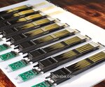
For your information We are attaching schematic as Well Solenoid Image.. As shown in the image We will connect the PCBs at the top edge of solenoids. Inside the solenoids there will be 16 pins that will exactly seat over the PCB test pads..electronic-jacquard-parts-M5-module-staubli-type.jpgTop.PNGBot.PNG

- - - Updated - - -

Upper left corner, obviously.

- - - Updated - - -


Yes, I did, although unwillingly. We are not in reverse engineering contest here and can expect a regular schematic, isn't it?

Schematics are given for your informationDrivers Sch.PNG

- - - Updated - - -

Sorry, my fingers and brain had a faulty data link. I meant any applied voltage up to the rated voltage should not cause problems. It follows that your 25V rated capacitor should be quite safe with 15V across it but you could even use one rated at anything from 15V or higher.

I suspect the combined impedances of the supply and ground wiring, including the ground plane are high enough that the fly-wheeling diodes raise the voltage much higher than 15V. The diodes 'dump' the energy into the supply which in most cases is able to absorb it safely but if you introduce impedance in the wiring, such as your ribbon cable, it will produce a voltage spike instead. I can't think of any other mechanism that would cause catastrophic failure in a ceramic capacitor.

If you add a Zener diode across the supply it will do no harm but it buys you free reverse voltage protection and will clamp anything above Zener knee voltage. I suggest 18V because it is higher than 15V but not as high as 25V. You can use a small (~0.5W) type because it will only be passing current for brief intermittent periods.

Brian.

Hello,
As per your input We will add Zener diode across the power supply.. I hope I will not create us to some other problem!
 

free wheeling diodes go directly across the solenoid. they are not necessarily connected to ground
1 solenoid, 1 free wheeling diode, unlike the ULN2803, where the 8 solenoids are connected to 8 diodes since its a power and ground connections

what limits the current in the solenoid when on?

Is the capacitor that burns up is C1 on the 15V line into a three terminal regulator. or C2 on the 5V on output of the three terminal regulator?
(or is it somewhere else that I missed?)
the solenoids appear to be powered by 12V. where is the 12 V supply?
how are the grounds for the 15V, 5V, and 12V supplies related?
 
The new posts are partly confusing the problem. We originally had a single side PCB, I understand that the failure reports are related to it. If not, why are you posting the picture in post #1 at all?

Now you posted pictures of a double sided PCB. How are they related to the originally reported problem? There are also conflicting 12V and 15V supplies. According to my analysis, it's a pure fake. Both posted boards have a single input, supplying the 7805 regulator input, 2803 free-wheeling pin and the solenoids. Shorted capacitor was connected to this "12"/15V input according to previous posts.
 

Hi,

another confusion:
The LEDs are connected to "VCC" --> Where is the VCC supply?

Btw: Even the 2 Layer PCB includes no true GND plane. Your GND is cut in many pieces and long - high impedance - traces. This is no reliable PCB layout.
It seems the person who did the PCB layout still thinks only about "DC" signals no "HF". He/she seems to have no isdea about "impdeance" and "EMI / EMC".
I recommend to learn how to design PCB for nowadays requirements.

Klaus
 

470K resistors in series with the LEDs will make them seriously dim! The PIV rating of the LEDs will almost certainly be exceeded with 7V (or is it 10V?) across them when the solenoid is turned off. R10 - R17 should go to the solenoid supply via suitably valued resistors.

Brian.
 
free wheeling diodes go directly across the solenoid. they are not necessarily connected to ground
1 solenoid, 1 free wheeling diode, unlike the ULN2803, where the 8 solenoids are connected to 8 diodes since its a power and ground connections

what limits the current in the solenoid when on?

Is the capacitor that burns up is C1 on the 15V line into a three terminal regulator. or C2 on the 5V on output of the three terminal regulator?
(or is it somewhere else that I missed?)
the solenoids appear to be powered by 12V. where is the 12 V supply?
how are the grounds for the 15V, 5V, and 12V supplies related?

Hello!
According to you ULN2803 is not needed to ground in our application. Am I right?? Unfortunately without ground ULN IC will not make any sense.

C2 Capacitor is burning up frequently that is placed across the 15V and Gnd.

Dont get confuse with 12V and 15V. Only We using 15V. Customer requirement was 12V initially. Later he changed to 15V. Since We have not Changed anything on PCB lay out.. For good practice We will change

We have a FRC header. From that We getting VCC for LED. We have slave board for LED power...

Nothing We have done for current limitation of Solenoid? Is it a serious issue to be consider?

- - - Updated - - -

470K resistors in series with the LEDs will make them seriously dim! The PIV rating of the LEDs will almost certainly be exceeded with 7V (or is it 10V?) across them when the solenoid is turned off. R10 - R17 should go to the solenoid supply via suitably valued resistors.

Brian.

Hi,
Practically you are correct. But visibility of LED is fine for us. So We have not think about the Resistors of LED.

I dont think Series resitor of LED will cause some problems. Current flowing path will be different for LED as well as solenoid.. What would be the result if We place correct value of Resistance..? Other than LED brightness?

- - - Updated - - -

Hi,

another confusion:
The LEDs are connected to "VCC" --> Where is the VCC supply?

Btw: Even the 2 Layer PCB includes no true GND plane. Your GND is cut in many pieces and long - high impedance - traces. This is no reliable PCB layout.
It seems the person who did the PCB layout still thinks only about "DC" signals no "HF". He/she seems to have no isdea about "impdeance" and "EMI / EMC".
I recommend to learn how to design PCB for nowadays requirements.

Klaus

VCC is from 14 Pin Header( From another Board).. We accept your points that PCB designer has no IDEA about the points you have mentioned( EMI,EMC and Impedance)

Better you can suggest any links regards that..

But do you think this will be problem for Capacitor burst?? Really?
 

Status
Not open for further replies.

Similar threads

Part and Inventory Search

Welcome to EDABoard.com

Sponsor

Back
Top