Maji
Newbie level 3
IR2110 simulation problem in OrCad Pspice
Hello everyone!
I was trying to simulate for some time an H bridge inverter driven by two IC circuits "IR2110", but i can't seem to go through it.
And since I'm new to this whole simulation things, i couldn't have any idea what do i have to change and how should i proceed to figure out the solution to this error
The error problem goes as the following:
It seems that a lot of voltages/ currents aren't converging :
The circuit i'm trying to simulate :
the netlist :
I'm sincerely grateful for the the time you spent reading/helping on this thread!
Hello everyone!
I was trying to simulate for some time an H bridge inverter driven by two IC circuits "IR2110", but i can't seem to go through it.
And since I'm new to this whole simulation things, i couldn't have any idea what do i have to change and how should i proceed to figure out the solution to this error
The error problem goes as the following:
Code:
Resuming Simulation with the following settings
RELTOL = 0.0086


INTERNAL ERROR -- Overflow, Convert

ABORTING SIMULATION"
It seems that a lot of voltages/ currents aren't converging :
Code:
Convergence problem in transient analysis at Time = 184.8E-09
Time step = 97.34E-18, minimum allowable step size = 100.0E-18
These voltages failed to converge:
V(N02921) = 70.48mV \ 70.63mV
V(X_U3.g1) = 14.70V \ 14.82V
V(X_U3.d1) = 50.08V \ 50.20V
V(X_U3.s1) = -149.08mV \ -31.01mV
V(X_U3.s2) = -56.36mV \ 61.72mV
V(X_U3.g2) = 14.71V \ 14.83V
V(X_U3.d2) = 42.51V \ 42.63V
V(X_U3.21) = 50.08V \ 50.20V
V(X_U3.c) = 42.51V \ 42.63V
V(X_U3.a) = 14.71V \ 14.83V
V(X_U3.b) = 42.51V \ 42.63V
V(X_U3.d) = -13.09V \ -12.97V
V(X_U4.g1) = 219.44mV \ 265.36mV
V(X_U4.s1) = -392.64mV \ -346.72mV
V(X_U4.s2) = -392.56mV \ -346.64mV
V(X_U4.g2) = 221.92mV \ 267.84mV
V(X_U4.a) = 221.94mV \ 267.86mV
V(X_U5.g1) = 14.37V \ 14.40V
V(X_U5.d1) = 321.38mV \ 351.89mV
V(X_U5.s1) = -34.04mV \ -3.538mV
V(X_U5.s2) = -30.32mV \ 189.94uV
V(X_U5.g2) = 14.35V \ 14.38V
V(X_U5.d2) = 17.55mV \ 48.05mV
V(X_U5.21) = 321.38mV \ 351.89mV
V(X_U5.c) = -14.62V \ -14.59V
V(X_U5.a) = -283.14mV \ -252.63mV
V(X_U5.b) = 14.35V \ 14.38V
V(X_U5.d) = 28.69V \ 28.72V
V(X_U6.g1) = 597.40mV \ -1.527V
V(X_U6.d1) = 15.65V \ 13.53V
V(X_U6.s1) = 597.56mV \ -1.527V
V(X_U6.s2) = 597.56mV \ -1.527V
V(X_U6.g2) = 596.95mV \ -1.528V
V(X_U6.d2) = 15.65V \ 13.53V
V(X_U6.21) = 15.65V \ 13.53V
V(X_U6.c) = 15.65V \ 13.53V
V(X_U6.a) = 596.96mV \ -1.528V
V(X_U6.b) = 15.65V \ 13.53V
V(X_U6.d) = -14.46V \ -16.58V
V(X_D1.4) = 76.30mV \ 74.64mV
These supply currents failed to converge:
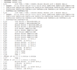
I(X_U1.V_MD4_RS_V1) = -2.090A \ -2.085A"The circuit i'm trying to simulate :
the netlist :
Code:
.EXTERNAL OUTPUT Vin2
.EXTERNAL OUTPUT Vin1
X_U1         +15V VIN1 0 VIN2 0 N04951 N01620 N01238 +15V 0 N04893 IR2110
+  PARAMS:  T1=-40 T2=25 T3=125 V1=10 V2=15 V3=20 TONT1=90N TONT2=120N TONT3=170N
+  TONV1=140N TONV2=120N TONV3=100N TOFFT1=77N TOFFT2=94N TOFFT3=130N TOFFV1=115N
+  TOFFV2=94N TOFFV3=75N TONVDD1=125N TONVDD2=120N TONVDD3=115N TOFFVDD1=113N
+  TOFFVDD2=94N TOFFVDD3=72N
X_U2         +15V VIN2 0 VIN1 0 N02388 N02921 N02864 +15V 0 N03056 IR2110
+  PARAMS:  T1=-40 T2=25 T3=125 V1=10 V2=15 V3=20 TONT1=90N TONT2=120N TONT3=170N
+  TONV1=140N TONV2=120N TONV3=100N TOFFT1=77N TOFFT2=94N TOFFT3=130N TOFFV1=115N
+  TOFFV2=94N TOFFV3=75N TONVDD1=125N TONVDD2=120N TONVDD3=115N TOFFVDD1=113N
+  TOFFVDD2=94N TOFFVDD3=72N
X_U3         +50V N01021 0 BSC440N10NS3_L0
X_U4         +50V N02423 0 BSC440N10NS3_L0
X_U5         N02864 N03095 0 BSC440N10NS3_L0
X_U6         N01238 N01859 0 BSC440N10NS3_L0
X_D1         +15V N02921 SMBD7000/INF
X_D2         N01021 N04951 SMBD7000/INF
X_D3         +15V N01620 SMBD7000/INF
X_D4         N02423 N02388 SMBD7000/INF
X_D5         N03095 N03056 SMBD7000/INF
X_D6         N01859 N04893 SMBD7000/INF
R_R1         N04951 N01021  10 TC=0,0
R_R2         0 N03095  1k TC=0,0
R_R3         N02423 N02388  10 TC=0,0
R_R4         N04893 N01859  10 TC=0,0
R_R5         N03095 N03056  10 TC=0,0
R_R6         0 N01021  1k TC=0,0
R_R7         0 N02423  1k TC=0,0
V_V1         +50V 0 50Vdc
V_V2         +15V 0 15Vdc
V_V6         VIN1 0
+PULSE 10V 0V 0 0 0 0.00001s 0.00002s
V_V7         VIN2 0
+PULSE 0V 10V 0 0 0 0.00001s 0.00002s
C_C1         N01238 N01620  1u IC=5V TC=0,0
R_R8         0 N01859  1k TC=0,0
L_L1         N05212 0  2mH
C_C2         N02864 N02921  1u IC=5V TC=0,0
R_R9         0 N05212  10m TC=0,0
I'm sincerely grateful for the the time you spent reading/helping on this thread!
Attachments
Last edited:
")


