T
treez
Guest
Hello,
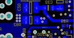
The Resistor shown (R82) is a 2010 size current sense resistor of a 60W PFC’d Flyback LED driver.
It dissipates 380mW.
The enclosure is plastic and has no vent holes.
The PCB layout guy said he had to use the thermal reliefs as shown, rather than solidly connecting the left hand pad to the copper plane. Is this right?...i thought for 2010 resistors, they could be soldered in without such aggressive thermal reliefing?
Anyway, we have actually found an all metal, 2010 resistor which looks like it can handle up to 275degC..
WSLT2010R2200FEA18
https://www.vishay.com/docs/30138/wslt2010.pdf
…do you agree that the WSLT series resistor would even be able to handle the 380mW of dissipation even with just being on a minimal pad, without even the thermal reliefs?
Attachments
Last edited by a moderator:
") .
.