Continue to Site

Welcome to EDAboard.com

Welcome to our site! EDAboard.com is an international Electronics Discussion Forum focused on EDA software, circuits, schematics, books, theory, papers, asic, pld, 8051, DSP, Network, RF, Analog Design, PCB, Service Manuals... and a whole lot more! To participate you need to register. Registration is free. Click here to register now.

Post layout simulation results differ from prelayout simulation- S21 is negative

Status
Not open for further replies.

sp.bhuvana

Newbie level 5
Joined
Feb 20, 2019
Messages
8
Helped
0
Reputation
0
Reaction score
0
Trophy points
1
Activity points
64
Hi,
Iam a beginner in cadence Virtuoso...
Iam working on LNA, In prelayout simulation, S11 = S22 < -10dB; S21 = 20dB; S12 <-30dB;
In post layout Simulation,
S11 = S22 < -10dB; S21 = -10dB; s12 < -30dB
Iam getting negative gain...
Can anyone tell me what may be the reason for negative gain?? Kindly help me...
 

We cannot judge without information of layout and its' parasitic elements.If especially the frequency is too high, layout parasitic components which have been extracted may play very important degradation role.
 

We cannot judge without information of layout and its' parasitic elements.If especially the frequency is too high, layout parasitic components which have been extracted may play very important degradation role.

Hi,
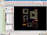
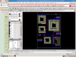
The Layout of LNA is designed for 5GHz
Herewith i have attached the LNA layout and RCX image for your reference,
Kindly check it..
Pls tell me what should i do???
 

Attachments

  • lna-layout.png
    lna-layout.png
    130.7 KB · Views: 133
  • lna-rcx.png
    lna-rcx.png
    125.5 KB · Views: 140

Now you need to look at the extracted netlist and carefully reason about the parasitics. Find the aggressor. With that new information, you can go back to your layout and apply changes to overcome parasitics. This is analog layout 101. Iterate, iterate, iterate.
 

How have you extracted the layout parasitics? I also see inductors in your layout.. How have you extracted them?
 

The Interconnections are very thin as I could see..They will bring extra inductances.
Have you ever simulated the whole layout in a EM Simulator ?? This is very important because Extraction Tools cannot predict Inductances accurately.
I recommend you to simulate whole layout in ADS using with RFPRO feature..
 

First thing to check is - whether your inductors were extracted as R parasitics, or defined as p-cells or cells that are blackboxed for extraction.
If it's the former - you have a big problem, because now instead of inductance you have resistance.
 

The Interconnections are very thin as I could see..They will bring extra inductances.
Have you ever simulated the whole layout in a EM Simulator ?? This is very important because Extraction Tools cannot predict Inductances accurately.
I recommend you to simulate whole layout in ADS using with RFPRO feature..

Hi,
As u said, i have increased the thickness of routing lines, my gain increased to positive(s21=7dB(In prelayout simulationS21 = 20dB); but frequency shifted to 7.9GHz)... still working on it...
Thank you...
 

Status
Not open for further replies.

Part and Inventory Search

Welcome to EDABoard.com

Sponsor

Back
Top