Continue to Site

Welcome to EDAboard.com

Welcome to our site! EDAboard.com is an international Electronics Discussion Forum focused on EDA software, circuits, schematics, books, theory, papers, asic, pld, 8051, DSP, Network, RF, Analog Design, PCB, Service Manuals... and a whole lot more! To participate you need to register. Registration is free. Click here to register now.

Lm317 input and output pin voltage specification

Status
Not open for further replies.

syeda amna

Full Member level 4
Joined
Jun 1, 2010
Messages
222
Helped
24
Reputation
48
Reaction score
22
Trophy points
1,308
Location
Pakistan
Activity points
2,551
Hello,
Can anybody explain constant current mode and constant voltage mode in LM317.
I have read Vin>Vout, Vin must be 3V higher than Vout, In this case we get the regulation property.
 

Hi,

There are so much explanations in the net, even video tutorials about LM317 current source.
Please go through a couple of them.
Then if there are still questions, please refer to one if these explanations.

In short: LM317 regulates for a constant voltage across two of it's pins. If you niw connect a resistor across these two pins: Then (according Ohm's law) you get a constant current.

Klaus
 

Adding to what Klaus stated, to minimum overhead IS about 3V but if you are using it as a constant current device, you have to add the voltage dropped across the load resistor. It is not the best device to use for constant current applications, a fixed voltage regulator works better.

If you want a constant current from a constant voltage, it will work well. You decide the voltage, make sure there is at least 3V more at the input pin and take the output through a fixed value resistor according to Ohms Law.

Brian.
 

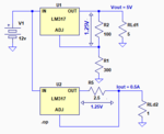
The LM317 regulates by keeping the OUT pin voltage greater than the ADJ pin voltage by 1.25V under all conditions (within its regulating current and voltage range).

So, if you use two resistors between the output and ground, with the ADJ pin going to the junction, it gives a constant-voltage output based upon the ratio of the two resistors, with 1.25V across the top resistor.

If you connect one resistor between OUT and ADJ and take the output from the resistor-ADJ junction you will get a constant-current output, again since it will maintain 1.25V across the resistor.

The two circuits are illustrated below:

Make sense?

Capture.PNG
 
Last edited:

Status
Not open for further replies.

Similar threads

Part and Inventory Search

Welcome to EDABoard.com

Sponsor

Back
Top