Continue to Site

Welcome to EDAboard.com

Welcome to our site! EDAboard.com is an international Electronics Discussion Forum focused on EDA software, circuits, schematics, books, theory, papers, asic, pld, 8051, DSP, Network, RF, Analog Design, PCB, Service Manuals... and a whole lot more! To participate you need to register. Registration is free. Click here to register now.

VHDL code flow in ISE Design Suite 14.7

Status
Not open for further replies.

prakash_kadri

Member level 2
Joined
Apr 11, 2013
Messages
42
Helped
0
Reputation
0
Reaction score
0
Trophy points
1,286
Location
Bangalore
Activity points
1,721
VHDL code flow in Xilinx ISE Design Suite 14.7

hi,

Is it possible to see code sequence in VHDL using Xilinx ISE Design Suite 14.7? I want to know which code line executes one after the other when the program is running. Hope you understood what I am trying to ask.
 
Last edited:
Vhdl is not a programming language, and is not executed inside an FPGA. It describes hardware. So you cannot do line by line debug as all hardware runs in parallel.

Xilinx has chipscope tool to debug hardware signals
 
Vhdl is not a programming language, and is not executed inside an FPGA. It describes hardware. So you cannot do line by line debug as all hardware runs in parallel.

Xilinx has chipscope tool to debug hardware signals

Thanks for the clarification. I am new to VHDL , so asking silly questions. thanks.

- - - Updated - - -

I have below VHDL code for RC Servo motor. I am using Spartan-6. When I execute the program the Servo moves to 180 degree position and again comes back to 0 degree position and it happens continuously. Why it is so? Is it the signal 'divrel1' reset to initial value of '1' every time?

Code VHDL - [expand]
1
2
3
4
5
6
7
8
9
10
11
12
13
14
15
16
17
18
19
20
21
22
23
24
25
26
27
28
29
30
31
32
33
34
35
36
37
38
39
40
41
42
43
44
45
46
47
48
49
50
51
52
53
54
55
56
57
58
59
60
61
62
63
64
65
66
67
68
69
70
71
72
73
74
75
76
77
library IEEE;
use IEEE.STD_LOGIC_1164.ALL;
use IEEE.NUMERIC_STD.ALL;
 
entity SPI_Servo is
    Port ( SERVO1   : out  STD_LOGIC;  
            
           i_clock  : in  STD_LOGIC);
end SPI_Servo;
 
architecture Behave of SPI_Servo is
signal divrel1 : integer range 0 to 1500 := 1;
signal div1us  : integer range 0 to 49  := 0;
signal div1ms  : integer range 0 to 999 := 0;
signal div10ms : integer range 0 to 9   := 0;
signal us1     : std_logic;
signal ms1   : std_logic;
signal ms10  : std_logic;
 
 
signal servocnt1 : integer range 0 to 20000 := 0; -- = 20ms
signal servoloc1 : std_logic;


begin
 
process begin
    wait until rising_edge(i_clock);
    us1  <= '0';
    ms1  <= '0';
    ms10 <= '0';
     if(div1us<49) then
       div1us <= div1us+1;
    else
       div1us <= 0;
       us1    <= '1';
       if(div1ms<999) then
          div1ms <= div1ms+1;
       else 
         div1ms <= 0;
       ms1    <= '1';
         if(div10ms<9) then  
             div10ms <= div10ms+1;
          else
            div10ms <= 0;
             ms10    <= '1';
        end if;       
      end if;
    end if;
end process;
 
  -- every microsecond
process begin
    wait until rising_edge(i_clock);
    if (us1='1') then
       if (servocnt1<19999) then  servocnt1<=servocnt1+1;
       else                      servocnt1<=0;
                                 
       end if;
     end if;
    if (servocnt1=0)          then servoloc1 <= '1'; end if; 
    if (servocnt1= 500+divrel1) then servoloc1 <= '0';end if; 
    
end process;


process begin
    wait until rising_edge(i_clock);
     If (ms10='1') then
        if(divrel1<2100) then divrel1 <= divrel1+10; end if;
     end if;
     
end process;
 
 SERVO1 <= servoloc1;


Reviewing your code can help. Look at the integer range definition of divrel1. Range of 0 to 1500 is implemented as 11 bit unsigned in synthesis, thus it overflows to zero before reaching 2100.

Although FPGA code isn't executed sequentially line by line, as TrickyDicky explained, it can be debugged almost like sequential code in a simulator like Modelsim.
 
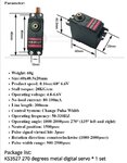
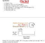
I got stuck in my project. Small servo(MG90S) works perfectly with the above program. But when I connect little bigger servo(KS3527), it looks like the power is not enough and I can hear buzz... sound from inside the casing. In scope I am seeing the PWM signal.I am using 5V , 5A normal power adaptor. I read somewhere in the article that , servo will draw large current at the beginning. so I connected 100uf Capacitor(Later tried 200 uf, 300uf, 400uf, 500uf as well) across the power supply. But still the issue is same. BTW servo is not under any load. Do the servo need 5V SMPS ?


MG90S.jpg
KS3527.JPG
Power Adapter.jpg
 
Last edited:

Are you sure that the supplied servo signal is regular (not rapidly varying pulse width)? Otherwise, follow the manufacturer data sheet. Current consumption of servos is beyond the topics of programmable logic.
 
Are you sure that the supplied servo signal is regular (not rapidly varying pulse width)?.

Yes. I am sure the pulse width is not rapidly varying. I tried with increment of "1" for "divrel1"in the below code line. The issue remains the same. So now I ordered 5V 20A SMPS to try.

if(divrel1<2100) then divrel1 <= divrel1+10;
 

What are your constraints about output ports?
DRIVE constraint may help you. For more information look for it in the Constraints Guide for ISE:
Code:
INST “instance_name” DRIVE= { 2 | 4 | 6 | 8 | 12 | 16 | 24 };
12 mA is the default.
 

Status
Not open for further replies.

Similar threads

Part and Inventory Search

Welcome to EDABoard.com

Sponsor

Back
Top