Continue to Site

Welcome to EDAboard.com

Welcome to our site! EDAboard.com is an international Electronics Discussion Forum focused on EDA software, circuits, schematics, books, theory, papers, asic, pld, 8051, DSP, Network, RF, Analog Design, PCB, Service Manuals... and a whole lot more! To participate you need to register. Registration is free. Click here to register now.

2.5V Micropower shunt voltage reference

Status
Not open for further replies.

Winsu

Full Member level 3
Joined
Oct 25, 2017
Messages
174
Helped
2
Reputation
4
Reaction score
4
Trophy points
18
Activity points
1,691
Hi All,

I have an application where the input voltage will be from 9V to 18V. I need to output a Voltage reference of 2.5V ( or around, between 6V and 2V ) and I'm not sure what means Min operating current( max Colum).

I'm thinking to use the TS4040 and I'm setting my resistance as 162.5K, with that a guarantee a 40uA at 9V, but when I raise the voltage to 18V the current goes to 95uA. It is above the Max minimum operating current. Am I putting in risk the TS4040?. What is the maximum current it could take?
 

Hi,

"min operating current" means the shunt reference diode needs a minimum current to work properly.

Let´s say:
* the Ref datasheet says: min operating current = 1mA
* and your application draws 0.2mA from this reference voltage node

Then the max. current limiting resistor needs to be calculated for (1mA + 0.2mA) 1.2mA @ lowest input voltage.

R_V_max = (V_in_min - V_ref) / (I_min_ref + I_max_app)


Klaus
 

You are reading the datasheet incorrectly. Is a matter of words.

The parameter minimum operating current, (meaning at least) is 40uA typical.
But it is terrible design practice to employ typical ratings. You should use at least 65 uA. Which for the minimum operating current parameter, its maximum rating means the worst case that the reference is guaranteed to operate properly.

For the maximum current the device can safely operate long term without damage, you have to go to the maximum operating current, which is 15 mA.
 

It's tough to design a very low minimum current reference,
you end up with huge resistors and subject to all of the low
current nonidealities (beta rolloff, subthreshold slope variation,
leakage floor, etc.) your available devices may exhibit. There
are however a lot of new products in this space aiming at
the IoT and handhelds, all very power-draw sensitive. You
ought to broaden your search.

You also express hardly anything in the way of specs other
than a silly-wide range of acceptable reference voltage (and
no mention of accuracy required, across what temp range,
etc.).

It might be that a good zener (maybe stacked on top of a
diode, which is called a "temperature compensated zener" if
it's done on one discrete-diode die) with an acceptably low
knee current could do the job - 6.1 - 6.2V is the norm for
these, a post-divider could scale it -if- the reference voltage
load is low and varies little (like, bias at 40uA, throw 10uA
down the divider and 30uA at the zener).
 

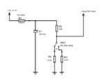
I actually did a first draft using a Zener, but I though that I would dissipate more watts in the 300ohm resistance than using the TS4040. would it be the case with the schematic I'm posting?.


Zener Draft.PNG


Cheers
 

Attachments

  • Analog Dimming.PDF
    11.2 KB · Views: 42

Hi,

P = V × I

This is always true, independent of diode type, resistor, LED or any other device...

But usually a zener needs higher current to stabilize the voltage.

Klaus
 

Status
Not open for further replies.

Part and Inventory Search

Welcome to EDABoard.com

Sponsor

Back
Top