Continue to Site

Welcome to EDAboard.com

Welcome to our site! EDAboard.com is an international Electronics Discussion Forum focused on EDA software, circuits, schematics, books, theory, papers, asic, pld, 8051, DSP, Network, RF, Analog Design, PCB, Service Manuals... and a whole lot more! To participate you need to register. Registration is free. Click here to register now.

Avoiding the crystal filter or multi-band phaser in multi-band SSB transceiver.

Status
Not open for further replies.

neazoi

Advanced Member level 6
Joined
Jan 5, 2008
Messages
4,122
Helped
13
Reputation
26
Reaction score
15
Trophy points
1,318
Location
Greece
Activity points
36,951
I was thinking of a way to remove the need for a crystal filter (filter method), or a multi-band phaser circuit (phasing method), in a multi-band SSB HF transceiver, without the use of a quadrature DDS or frequency division of a higher frequency oscillator for phasing.

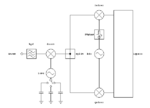
I came up with this diagram. It is a single frequency (IF) quadrature transceiver block, combined with a superhet RF front end.

The quadrature block will work in the IF only, to reject the opposite sideband, whereas the superhet image will be removed by the front end BPF. And since the quadrature block works only on one frequency, there is no need to readjust the phasing when the frequency of the transceiver is changed.
The front end oscillator is a wide range VFO, capable of covering the IF/LO difference.

I do not see the reason why it wouldn't, but will this actually work?
 

Attachments

  • Capture.PNG
    Capture.PNG
    7.7 KB · Views: 144

That's exactly how it is normally done. In most cases it doesn't make sense to produce tunable I & Q LO signals so down-mixing and a fixed IF is used. Similarly for transmitting, a low frequency signal is produced then up-mixed to TX frequency.

You probably want to add a filter at IF between the mixer and splitter to minimize LO breakthrough to the quadrature mixers.

Brian.
 
  • Like
Reactions: neazoi

    neazoi

    Points: 2
    Helpful Answer Positive Rating
That's exactly how it is normally done. In most cases it doesn't make sense to produce tunable I & Q LO signals so down-mixing and a fixed IF is used. Similarly for transmitting, a low frequency signal is produced then up-mixed to TX frequency.

You probably want to add a filter at IF between the mixer and splitter to minimize LO breakthrough to the quadrature mixers.

Brian.

That's perfect! Up to know I thought the only way ssb could be done, would be with hard to build crystal filters or hard to tune broadband phasers.
If the mixers in my diagram are bi-directional (eg sbl-1) then could this chain be used for TX as well? I mean, where does the sideband cancellation happen on TX, at the splitter?
 
Last edited:

If the mixers in my diagram are bi-directional (eg sbl-1) then could this chain be used for TX as well? I mean, where does the sideband cancellation happen on TX, at the splitter?
Yes and it is done commercially. The problem isn't completely solved though, for transmission you still have to mix two channels of audio with 90 degrees shift between them. The schematic you showed only refers to the RF quadrature carrier. If you can mix quadrature audio as well, swapping either the audio I with Q -or- the RF I with Q (both not both) will produce the other sideband.


Brian.

Why is the splitter required? Can't I just connect the two mixers inputs together and with the output of the first mixer?
 

Theoretically you could but the risk of one feeding the other would be very high and impedance matching would be tricky. A two way splitter gives isolation on all three ports and only costs a few resistors. Most mixer modules like the SBL-1 contain nothing but a small ferrite cored coil and four matched Schottky diodes, they work equally well if reversed or output is taken from the LO port so it would be expected that leakage and mixer products would be present on their other pins.

Brian.
 
  • Like
Reactions: neazoi

    neazoi

    Points: 2
    Helpful Answer Positive Rating
Theoretically you could but the risk of one feeding the other would be very high and impedance matching would be tricky. A two way splitter gives isolation on all three ports and only costs a few resistors. Most mixer modules like the SBL-1 contain nothing but a small ferrite cored coil and four matched Schottky diodes, they work equally well if reversed or output is taken from the LO port so it would be expected that leakage and mixer products would be present on their other pins.

Brian.

You mentioned resistor dividers, but it might be not suitable for this application due to their high loss, sinse low lever signals are goind to be splitted especially in receive. But nevertheless could they be used as combiners as well? or will it be tricky qith 3 ports as some of the power that is going to be combined will reach the other port that outputs its own power to be combined.

I have built and tested this **broken link removed** and it works at all HF frequencies as a splitter ok.
but I have not tested it for isolation between ports. Do you think it provides any isolation?
 
Last edited:

The splitter provides impedance matching and isolation between output ports. The post #1 scheme should also have isolation between the first and second mixer stage, usually an IF amplifier.
 
  • Like
Reactions: neazoi

    neazoi

    Points: 2
    Helpful Answer Positive Rating
The splitter provides impedance matching and isolation between output ports. The post #1 scheme should also have isolation between the first and second mixer stage, usually an IF amplifier.

Ok a filter and an IF amplifier that is clear. Will this **broken link removed** provide isolation?
 

Theoretically you could but the risk of one feeding the other would be very high and impedance matching would be tricky. A two way splitter gives isolation on all three ports and only costs a few resistors. Most mixer modules like the SBL-1 contain nothing but a small ferrite cored coil and four matched Schottky diodes, they work equally well if reversed or output is taken from the LO port so it would be expected that leakage and mixer products would be present on their other pins.

Brian.

I measured the coupler **broken link removed** isolation between ports and it is about 15db

but this one https://www.ab4oj.com/test/imdtest/images/fig9.gif has much more.

Does the splitter/combiner really need that much isolation in my circuit in post #1?
I worry that the second combiner has higher loss which should be inappropriate for RX purposes
 

Status
Not open for further replies.

Part and Inventory Search

Welcome to EDABoard.com

Sponsor

Back
Top