Continue to Site

Welcome to EDAboard.com

Welcome to our site! EDAboard.com is an international Electronics Discussion Forum focused on EDA software, circuits, schematics, books, theory, papers, asic, pld, 8051, DSP, Network, RF, Analog Design, PCB, Service Manuals... and a whole lot more! To participate you need to register. Registration is free. Click here to register now.

Optocoupler with LIVE wire

Status
Not open for further replies.

venkates2218

Full Member level 6
Joined
Sep 30, 2016
Messages
354
Helped
1
Reputation
2
Reaction score
1
Trophy points
1,298
Activity points
4,306
PC814.PNG

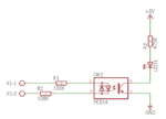
The input will vary from 150VAC to 280VAC.If the supply is available means the LED have to glow....
I'm new to this circuit.So I don't known in-depth.I tried with hardware,if the voltage is low means the LED not glowing,so I changed the resistance value to low(56K). If the resistor value is low means when high voltage across the IC become faulty.
If the resistance value is high means,at low voltage the LED not glowing...
How to solve this issue and to make the LED glow in specified voltage range.
 

Hi,

electronics works with voltage and current. you can´t calculate with "glow" or "faulty".
This is why there are datasheets. full of usueful values.

You need to specify at which input voltage RMS you want the LED safely to be OFF.
You need to specify at which input voltage RMS you want the LED safely to be ON.
(inbetween there is a grey area, LED might be OFF, dimmed, or ON)

*********
Input side resistors. Max current = min resistor value:
Optocoupler datasheets tells the max. input (LED) recommended operating current..
Input voltage is up to 280V RMS, this means 280V x 1.414 peak voltage.

Now it´s just ohm´s law: R = V / I --> R_L_min = peak_input_voltage / max_input_current.

Power dissipation of resistor: P = V^2 / R = 280V^2 / R_L
****
Go on this way.

Klaus
Image_2png.png

I removed the LED and it connected to controller for sensing purpose.And changed the resistor value to 5.5K 2WATTS.Now also their is no response from the optocoupler.The resistor is used as an pullup resistor for the controller.
 

Hi,

sadly still no useful specifications.

Your calculation of the resistor is wrong.
You calculated 5.5kOhms.

this gives 280V/5500Ohms = 50.1mA

According datasheet 50mA is the absolute maximum limit. Once you cross this limit, just for a short moment - you risk to kill the device.
50mA is NOT the usual operating current.
Now you should know that 280V is the RMS voltage and thus the maximum voltage is 280V x 1.414 = 396V
at 5.5kOhms this gives a maximum current of about 72mA --> expect the PC814 to be killed sooner or later.

The dissipated of the resistor power is in the range of 14W --> thus the 2W resistor will be killed, too.

This is very basic electronics stuff. You really should know this .. especially when dealing with dangerous high voltage.
I expect there is even more lack of technical knowledge... thus you risk your and other´s lives.

Please learn how to calculate and deal with voltage, current, resistance, power, AC waveform.. and how to treat dangerous high voltage (circuits)...

Klaus

What specification I have to give..?
About design or something else..?
 

Hi,

you didn´t read post#2?

Klaus

added:
did you try an internet search: "how to calculate optocoupler circuits"?
 

Image_3.pngSpec_1.pngSpec_1.png


This is my circuit.When the Input signal is available means the LED have to glow...
Normally input supply will be 230VAC.But the voltage may vary from the 160VAC to 280VAC(Maximum Voltage).
The controller have to sense the available of input voltage,and have to glow the LED,if the voltage is varying also means.

This is my requirement.
 
  • Like
Reactions: treez

    T

    Points: 2
    Helpful Answer Positive Rating
Calculated the resistor value for 5 different voltage range and averaged them.The final value is 11K...
Have to provide resistor on Negative input side also..?
 

2x 5.5k series resistor seems to keep the maximum input current ratings, but due to wide PC814 CTR range of 20 to 300%, there's no way to get a useful input voltage threshold (if required). You have apparently calculated the resistors to work with minimal CTR of 20%, the backside is that an opto coupler with 300 % CTR reduces the input threshold to below 15 VAC.

Not sure about your specification in this regard.
 

you could go for say 3mA opto LED current at mains peak (the minimum mains peak of the minimum mains that you want to bother detecting)
So mains peak at 160 vac is 226V.
So do 0.003 = 226/R

That gives you R.

Then be sure you size the opto transistor side pullup resistor to sucessfully get pulled down low enough when this 3mA flows...so you will have to see what is the min CTR at this 3mA current level.

Or are you doing a mains zero cross detector...if so, then you will have to do a bit of timing between highs and lows to get the zero cross.
 

Is their anyother way to detect the AC power supply..?
 

you could go for say 3mA opto LED current at mains peak (the minimum mains peak of the minimum mains that you want to bother detecting)
So mains peak at 160 vac is 226V.
So do 0.003 = 226/R

That gives you R.

Then be sure you size the opto transistor side pullup resistor to sucessfully get pulled down low enough when this 3mA flows...so you will have to see what is the min CTR at this 3mA current level.

Or are you doing a mains zero cross detector...if so, then you will have to do a bit of timing between highs and lows to get the zero cross.

The resistor is required for both phase and neutral or phase is enough..?
 

Positive_voltage.png


The optocoupler working fine with ground supply...I tried with positive voltage instead of ground supply and connected the output from the optocoupler to controller.Their is no response in the controller.Is this circuit is correct..?
 

You had a working configuration in post #3. Looks like you are trying hard to change it to non-working…

It's no problem to connect the controller input either to collector (inverting operation) or emitter (non-inverting). But there must be load resistor carrying the opto coupler output current. R17 in post #13 is an input series but no load resistor.
 

Hi,

Avery basic problem.

A microcontroller (as well as any ither logic device) input needs either true HIGH or true LOW.
The voltages and currents are given in the datasheets as: V_IH, V_IL, I_in...

Now your circut when active drives HIGH,
But when deactivated it just releases the signal. The signal is not driven LOW. It is floating, which means "undefined".

Thus you can't expect that your microcontroller detects LOW.

Klaus
 

You had a working configuration in post #3. Looks like you are trying hard to change it to non-working…

It's no problem to connect the controller input either to collector (inverting operation) or emitter (non-inverting). But there must be load resistor carrying the opto coupler output current. R17 in post #13 is an input series but no load resistor.

psoitive side.png

Is this correct..?
 

Hi,

According to what #14 and #15 say, it would seem so.

What's input high on the device out of the opto transistor?

(ignoring any voltage drop from collector to emitter...)
10k/11k = 0.909
0.9 * 5V = 4.54V

Is that enough to turn on whatever thing it is you're using? The thing you are using will have a datasheet on the Interweb that will explain in a funny-looking table thing somewhere beyond page 1 the input low and input high specifications.

I really recommend spending a shocking whole 5 minutes reading about open collector/open drain configuration. Think about how comparators work and how they won't work if something is missing... Make a discrete NPN inverter in a simulator or on a breadboard, vary the load resistance and see what happens, or just simulate this with a comparator IC. Then add a terribly time-consuming 5 minutes more (reading about, if necessary) thinking about how voltage dividers work. Then push it to the max. and have spent a whole 15 minutes on research and review pull-up and pull-down resistors and what they do. It will remove what looks like confusion. Have fun!
 
  • Like
Reactions: FvM

    FvM

    Points: 2
    Helpful Answer Positive Rating
Status
Not open for further replies.

Similar threads

Part and Inventory Search

Welcome to EDABoard.com

Sponsor

Back
Top