Puppet123
Full Member level 6
Hello,
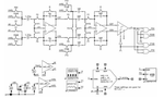
I want to simulate the following schematic of Discrete Time Sigma Delta Modulator straight from Schreier/Temes.
I am using Cadence Specture/Virtuoso for this, and must use this set up.
All blocks are behavioral and ideal using voltage controlled or current controlled sources except comparator which is transistor based. So switches, opamps are ideal.
It is attached and is the Figure WITHOUT the Figure notation below the schematic (SD1.png)
My questions:
1) What is the Reset signal ? When is it clocked or set ? Phi 1 or Phi 2 ?
2) How to create this Reset Signal ?
3) Comparator is Reset also. I know it is reset on Phi 2 ? But why ? On Falling or Rising Edge of Phi 2 ?
4) How to create this Reset Signal for the Comparator ?
These things are not explained in the text.
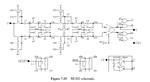
I included the behavioral simulation for the same 2nd Order Discrete Time Sigma Delta from new 2nd edition of Schreier/Temes.
It is attached and is the Figure WITH the Figure notation below the schematic (SD2.png)
I am totally confused about the reset scheme in that test bench - what is clocking the reset signals. These things are not explained in the text.
Can anyone help ?
Thank you.
I want to simulate the following schematic of Discrete Time Sigma Delta Modulator straight from Schreier/Temes.
I am using Cadence Specture/Virtuoso for this, and must use this set up.
All blocks are behavioral and ideal using voltage controlled or current controlled sources except comparator which is transistor based. So switches, opamps are ideal.
It is attached and is the Figure WITHOUT the Figure notation below the schematic (SD1.png)
My questions:
1) What is the Reset signal ? When is it clocked or set ? Phi 1 or Phi 2 ?
2) How to create this Reset Signal ?
3) Comparator is Reset also. I know it is reset on Phi 2 ? But why ? On Falling or Rising Edge of Phi 2 ?
4) How to create this Reset Signal for the Comparator ?
These things are not explained in the text.
I included the behavioral simulation for the same 2nd Order Discrete Time Sigma Delta from new 2nd edition of Schreier/Temes.
It is attached and is the Figure WITH the Figure notation below the schematic (SD2.png)
I am totally confused about the reset scheme in that test bench - what is clocking the reset signals. These things are not explained in the text.
Can anyone help ?
Thank you.
Attachments
Last edited: