Continue to Site

Welcome to EDAboard.com

Welcome to our site! EDAboard.com is an international Electronics Discussion Forum focused on EDA software, circuits, schematics, books, theory, papers, asic, pld, 8051, DSP, Network, RF, Analog Design, PCB, Service Manuals... and a whole lot more! To participate you need to register. Registration is free. Click here to register now.

Fast Switch circuit for -30V

Status
Not open for further replies.

eumesh49

Newbie level 3
Joined
Apr 24, 2017
Messages
4
Helped
0
Reputation
0
Reaction score
0
Trophy points
1
Activity points
44
Hi,
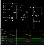
I am trying to build a switch circuit to switch upto -30Volts and to supply utp 5Amp. I need to generate a -30V test pulse for 100usec. So output should be either open or a 100usec, pulse.
I have transient pulse generator, but those generates either -30V or Zero voltage. I dont want that. I want either nothing or -30V. Please suggest if anyone have a idea.
I will highly appreciate it. I tried building using relays, but they are not good enough to have a 100usec pulse.

Thanks in Advance,
Umesh
 

Look at using a MOSFET.

I tried using FET, but I am not able to switch its gate while working in negative supply region. I tried different options but they does not help.
 

Of course you can switch a FET gate when it's positioned
negative, you just have to make the right circuit.

100uS is not fast at all.

You could make a (-30V + 5V) reference / power rail with
a 7805 regulator whose "GND" is -30V and "VIN" is your
local ground.

In that negative-referred 5V domain you could operate a
chubby 5V buffer as a gate driver (I have used parallel
74HC14 Schmitt inverters to drive logic level MOSFETs
at much faster than this). But I might suggest a GaN
FET (EPC, GaN Systems) as alternatives, they will be
much more "square" (do you care, or know whether to
care, about waveshape?).

Then the trick is to pass current down from a "+5 logic"
domain (0-5) to the negative domain (-30 - -25). One
scheme I use a lot is, use a PNP (or PMOS) cascode
(B or G = GND) and an inverter w/ series resistor driving
its emitter (source). Cascode will throw (VOH-Vbe)/Rseries
down to "something" at the negative domain. A same value
resistor would give you an adequate VOH, when driven by
that current, to drive a Schmitt gate. One drives 5 in the
hex logic gate chip, 5 drive FET. Simple enough.
 

Hi,

I tried different options but they does not help.
Show us your work with some description how you want it to operate.

Mind: A forum is meant that people help you to rectify problems with your circuit, it is not ment that other people design a complete new circuit for you.

Klaus

Added: Why don't you use a simulation tool, like LTspice?
 

By sending positive pulses through a series capacitor, you can convert the pulses into bipolar AC. This provides negative pulses to drive a P device which switches a negative supply. At other times the transistor is shut off, which is the same as high impedance.

**broken link removed**

The 555 outputs +5V pulses. It goes to 0V gnd for 100 uSec.
Notice the bias voltage goes negative for 100 uSec, turning on the transistor. The bias only needs to go down to -0.7V
The load receives -30V.
 

Attachments

  • pos pulses fm 555 thru cap drive neg PNP -30V 5A load.png
    pos pulses fm 555 thru cap drive neg PNP -30V 5A load.png
    18.3 KB · Views: 114

Hi,


Show us your work with some description how you want it to operate.

Mind: A forum is meant that people help you to rectify problems with your circuit, it is not ment that other people design a complete new circuit for you.

Klaus

Added: Why don't you use a simulation tool, like LTspice?

My apologies if I did not share the details of my implementation. I did not expect someone to do the design for me. I thought to put this question on forum to see if some one have something similar used before. Anyway, my implementation was simple, Connect the Source of a N-CH GET to negative supply. Have Source and gate connected using 100 ohm resistor. Drain is output.
Drive the gate using a N CH BJT with emitter is connected to gate. Collector at a bias voltage of 5V. Drive the base using a function generator with a diode in series.

This implementation works, but I can not get more than 2A from it. My output start getting clipped for more current. I was designing for 5A.,
 

Hi,

I can´t imagine your complete circuit ... thus a schematic would be very helpful - even hand drawn.

100 Ohms for R_GS is too low in my eyes.
Drive the FET using an optocoupler (or other coupler) for isolation.
A dedicated MOSFET driver will improve switching speed.

Don´t forget to add an overvoltage protection to the MOSFET in case of voltage spikes caused by (stray) inductance.


Klaus
 

Either you're FET has too much resistance (Rds) or you're not driving the gate hard enough to turn it completely on.
 

There are, today, isolated power MOSFET drivers. It
could be worth the searching, although they are more
expensive.
 

Status
Not open for further replies.

Similar threads

Part and Inventory Search

Welcome to EDABoard.com

Sponsor

Back
Top