Continue to Site

Welcome to EDAboard.com

Welcome to our site! EDAboard.com is an international Electronics Discussion Forum focused on EDA software, circuits, schematics, books, theory, papers, asic, pld, 8051, DSP, Network, RF, Analog Design, PCB, Service Manuals... and a whole lot more! To participate you need to register. Registration is free. Click here to register now.

Ptc Heater PID Control troble shooting..

Status
Not open for further replies.

lsh9640

Newbie level 2
Joined
Jul 30, 2018
Messages
2
Helped
0
Reputation
0
Reaction score
0
Trophy points
1
Activity points
28
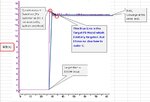
Ptc PID Control.jpg

Compute model :
Error = Target_Watt - Current_Watt
Current_Duty = Previous_Duty + GAIN * (Error)
→ I assume upper calculation is not a PI Modeling but
it approximately work as PI control.


※ There are a couple of problems I face
1) Watt scale ( 0 ~ 10000 ) is different with Duty scale ( 0 ~ 1500 )
→ So, I Step down Watt scale by setting GAIN like 0.1 or 0.05 (Overshoot worsen if I raise this GAIN Value)
2) Duty is not proportional to Watt
→ Duty - Watt characteristic is some what complicated, Let me say, 20% IGBT Duty ON is good enough to saturate PTC(means there is less chance to increase current by increasing Duty), and 30% IGBT Duty ON will result in saturation(no more current even if applying more Duty on IGBT )
3) Internal resistor which affect current volume is constantly changed by internal temperature.
→ It is getting more complicated so, I simply disregard 2) 3) factors

Is there anyway to get better result like BLUE Line on the graph?
Could anyone give me some idea how to solve this problem?
Thanks.
 

Hi,

PTC already is "regulated" somehow. Adding a second regulator (PID) may interfere.

*****
* To avoid the overshoot, you should increase the "D" part.
* to avoide constant deviation you should set the "I" to a positive value. With small "I" values it takes long time until it reaches the expected value. Wit too high vlaues it may become unstable.


Klaus

① I understand PTC regulate itself when operating, but it has to be precisely regulated (like 5000W +- 50W error tolerance) according to customer requirement spec. so i thought pi control is nessasery in this case


I understand I or D-gain would give a better result
But take a consideration this
Above equation already have Previous_Duty which I guess it partially include Integration GAIN properties..
what's worse,
**broken link removed**
② Error is usually calculated in this expression : e(t) = u(t) - y(t), In PI Control system.

But In the above PTC system, u(t) is Duty and y(t) is Watt. And these two variable are not linearly analyzed and also there are disturbance factors such as (PTC internal Temperature / WindSpeed / InletTemp) to make it literally impossible to expect behavior of PlantProcess as well as Transferfunction..

Based on this, what approach should i follow (finding transferfunction etc..)
 

Status
Not open for further replies.

Part and Inventory Search

Welcome to EDABoard.com

Sponsor

Back
Top