Kynix
Banned
A while ago I asked a question about driving a stepper motor using a 2N5550 and was advised that it wasn’t really capable/a good idea. I received a good answer but would like a bit more information really so that I can make these decisions for myself in the future.
2N5550
On the 2N5550 transistors PDF it says it can drive up to 600mA (DC) under the maximum ratings (am I interpreting this correctly?):
Ic Max rating
If this is correct, why does the DC Current gain graph only show up to 100mA, is this just because it can handle 600mA but would be almost pointless to actually use it for that because of the low gain at that level?

So this brings me to the 2N4401. The **broken link removed** also says the max collector current can be 600mA (again, am I interpreting this correctly?).
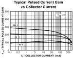
Now the current gain graph on this transistor shows it going up to 300mA however it says “pulsed” in the title of the graph and there doesn’t seem to be a graph for continuous so I’m a little confused why this might be? I suppose driving a stepper motor would come under the category of pulsed though?
So assuming that this is suitable for driving my 259mA stepper motor I would need to supply the base with about (259/150) 1.7mA (259 being the number of mA needed by the stepper motor and 150 being roughly the current gain (derived from the graph)?), is this correct?
I understand that from my other question I should really use a MOSFET as they are better suited to the job, I just have a handful of these 2N4401s kicking about that I thought I could test my code and theory with.
Thanks in advance and I’d appreciate a response to even the little questions I raised like the “am I interpreting this correctly?” ones, just to reassure me that I’m on the right lines (or not).
2N5550
On the 2N5550 transistors PDF it says it can drive up to 600mA (DC) under the maximum ratings (am I interpreting this correctly?):
Ic Max rating
If this is correct, why does the DC Current gain graph only show up to 100mA, is this just because it can handle 600mA but would be almost pointless to actually use it for that because of the low gain at that level?

So this brings me to the 2N4401. The **broken link removed** also says the max collector current can be 600mA (again, am I interpreting this correctly?).
Now the current gain graph on this transistor shows it going up to 300mA however it says “pulsed” in the title of the graph and there doesn’t seem to be a graph for continuous so I’m a little confused why this might be? I suppose driving a stepper motor would come under the category of pulsed though?
So assuming that this is suitable for driving my 259mA stepper motor I would need to supply the base with about (259/150) 1.7mA (259 being the number of mA needed by the stepper motor and 150 being roughly the current gain (derived from the graph)?), is this correct?
I understand that from my other question I should really use a MOSFET as they are better suited to the job, I just have a handful of these 2N4401s kicking about that I thought I could test my code and theory with.
Thanks in advance and I’d appreciate a response to even the little questions I raised like the “am I interpreting this correctly?” ones, just to reassure me that I’m on the right lines (or not).