Continue to Site

Welcome to EDAboard.com

Welcome to our site! EDAboard.com is an international Electronics Discussion Forum focused on EDA software, circuits, schematics, books, theory, papers, asic, pld, 8051, DSP, Network, RF, Analog Design, PCB, Service Manuals... and a whole lot more! To participate you need to register. Registration is free. Click here to register now.

Oscillator - astable

Status
Not open for further replies.

akshathavenkatesh

Newbie level 4
Joined
Jan 13, 2017
Messages
7
Helped
0
Reputation
0
Reaction score
0
Trophy points
1
Activity points
89
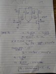
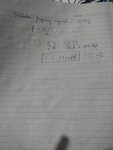
I want to design an astable multivibrator having oscillation frequency -300kHz. I have attached the calculation that I've done to achieve the target frequency and this works in LTspice . According to my understanding of an astable multivibrator, this is how it operates- initially I'm assuming one of the transistors to be on , say Q1 so now the potential at the collector of Q1 is 0V ideally and C1 starts charging through R1 and since C1 is connected to the base of Q2 , when the voltage reaches 0.7 V, Q2 switches on and C2 starts charging and this cycle continues . Could you let me know if I'm making some mistake in analysing this circuit.
 

Attachments

  • IMG_20180605_232841866.jpg
    IMG_20180605_232841866.jpg
    501.5 KB · Views: 84
  • IMG_20180605_232853189.jpg
    IMG_20180605_232853189.jpg
    503.7 KB · Views: 71

This circuit is based on the RS flip-flop using cross-coupled transistors. As you state, one capacitor charges while the other discharges, creating the oscillating behavior.

when the voltage reaches 0.7 V, Q2 switches on

Q1 needs to have its bias shutting it off at that time. It is possible to have a stagnant mode, when both transistors stay on. Stagnant mode might happen at power up if the circuit is symmetrical in all ways.

Each capacitor affects bias voltage of the opposite transistor. One feature which is not readily obvious, is that bias voltage of each transistor goes into the negative briefly.

I have a Youtube video of an animated simulation of the astable multivibrator. It portrays capacitors charging and discharging.


or

www.youtube.com/watch?v=HjSgdcgYnFk
 

I have not understood your question.

This is a standard circuit and usually works reliably. There are modifications for the "sure-start" option.

There will be some voltage dependence of the frequency and you need to be aware of that: the circuit need to be powered from a well regulated and well bypassed supply - that is all.

Please tell us specific problems that you encounter.
My specific problem is that I don't want the base resistor to be so high - I want it within 100kohm and increase the capacitors a little. But when I do this , the circuit doesn't work, as it no oscillations are observed.
 

On the other website you were told that an astable circuit in a simulation does not oscillate because the resistors, capacitors and transistors on each side are identical and that there is no noise to start the oscillations. A simulation is not real!
You were also told that your resistor values are much too high and your capacitor values are much too low.
so I have no way of knowing if my circuit works without building it on and checking it. Is that what you are saying.
 

Hi,

Not sure what software you are using. Some allow you to change the simulation settings to accomodate oscillators. You should search online for things like "bjt oscillator not oscillating in xyz software" in case it is a common known issue with the software you are using.

I think LTSpice is okay for oscillators from what I see other people posting, maybe that is worth a check if you don't want to /can't breadboard it or make a prototype.
 

so I have no way of knowing if my circuit works without building it on and checking it. Is that what you are saying.
On the other website you were told to make a .IC statement in LTspice to make the startup asymmetrical. You could also add some noise to make it like a real circuit will have.
Designing and building a transistor astable oscillator is so simple that I design and build it without simulating it. If the supply voltage is higher than about 7V then the Sim program doesn't know that the transistors will have emitter-base avalanche breakdown which messes up the oscillator.
 

The role of noise in oscillator startup is more a theoretical question. In practice power-on transients and circuit asymmetries are sufficient to start oscillation.

Respectively there's little use for a noise source in typical oscillator simulations. Skip initial transient solution (SPICE uic option) as suggested and in case of doubt a "kick start" pulse will start any oscillator.


I also agree with the comment about marginal resistor and capacitor dimensioning in the original circuit. Why would you select the base resistors for a B value > 500?
 

My specific problem is that I don't want the base resistor to be so high - I want it within 100kohm and increase the capacitors a little. But when I do this , the circuit doesn't work, as it no oscillations are observed.

This is really strange; is that a real circuit or only a simulation? As other wise men have mentioned, a simulation may not work for a symmetrical circuit. If the base resistor is too high, the base current may be low and the transistor may not switch on hard.
 

Use a CD4047 IC. it oscillates with a single RC timing capacitor and resistor. It works with a supply as low as 3V and has a divide-by-two frequency divider that produces a perfect 50-50 squarewave. Its datasheet shows RC values for various frequencies up to 1MHz.
 

Status
Not open for further replies.

Part and Inventory Search

Welcome to EDABoard.com

Sponsor

Back
Top