Continue to Site

Welcome to EDAboard.com

Welcome to our site! EDAboard.com is an international Electronics Discussion Forum focused on EDA software, circuits, schematics, books, theory, papers, asic, pld, 8051, DSP, Network, RF, Analog Design, PCB, Service Manuals... and a whole lot more! To participate you need to register. Registration is free. Click here to register now.

Input and Output Voltage of OPA

Status
Not open for further replies.

Johnny_YU

Member level 2
Joined
Oct 17, 2013
Messages
45
Helped
2
Reputation
4
Reaction score
2
Trophy points
8
Activity points
371
Hi,All

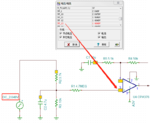
In my Schematic , 1.5V should be detected on the positive input of OPA, and the output voltage should be 1.5V.

I use TINA to simulate the circuit , it shows the positive input of OPA is 1.494V,and the output voltage is 1.4948V.

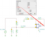
But, When I test this circuit , I found that the positive input of OPA is about 220mV , the output voltage is 1.5V.

Why the positive input of OPA is 220mV? And Why the output voltage is still 1.5V?
 

Attachments

  • Positive Input Pin of OPA.png
    Positive Input Pin of OPA.png
    31.5 KB · Views: 200
  • Output Pin of OPA.png
    Output Pin of OPA.png
    31.4 KB · Views: 151

Because you tested it wrongly, e.g. measured the voltage with a too low input resistance instrument. Presumedly the voltage Vin+ voltage was only 220 mV while you connected the meter. Problem is 4.7M resistor R1.
 
Hi,

I don't understand the set-up there, for example the capacitor C1. What does that do, please?

That's a non-inverting amplifier with a gain of 10 or does it just look like one?

If so, the divider and gain stage don't seem to match up, to me - input * 10 makes for a very overloaded 376 - it can only operate to 5V in and out (but I know in simulations it looks like it can do a lot of things it can't according to the the OPA376 datasheet).

How does that circuit work, please? Does it divide down the input and multiply the output or are the parts around In+ for some other purpose?
 

HI,

it is an non inverting amplifier circuit with some kind of high pass filtering. (low frequencies are attenuated with respect to AC frequencies)
* the capacitor makes the DC gain to become "1"
* while the resistors make the AC gain to be "10.8"

In opposite to a true HPF - where DC gain is "0" - here in this circuit you have two "corner frequencies".
* One is (going from DC to higher frequencies) where the gain "leaves" the gain_of_one line (lower corner frequency, calculate with C1, (R5+R4) )
* and the other is where the gain enters the "10.8" gain (upper corner frequency, calculate with C1, R5).
You may calculate theses corner frequencies like the usual -3dB cutoff frequencies, but because of the setup they are not -3dB. It depends on part values.

The gain graph is:
* Gain = 1 at DC
* horizontal line with gain = 1, up to the lower corner frequency
* then a rising line from lower corner frequency to upper corner frequency, from gain =1 to gain = 10.8
* then a horizontal line with gain = 10.8 (until the limit of the OPAMP)

Klaus
 
Because you tested it wrongly, e.g. measured the voltage with a too low input resistance instrument. Presumedly the voltage Vin+ voltage was only 220 mV while you connected the meter. Problem is 4.7M resistor R1.

Hi, FvM
Thank you for your reply!
You are right. When I use a Multimeter(HIOKI DT4211), Vin+ is about 600mV. When I use a oscilloscope, Vin+ is about 220mV.

- - - Updated - - -

Hi,

I don't understand the set-up there, for example the capacitor C1. What does that do, please?

That's a non-inverting amplifier with a gain of 10 or does it just look like one?

If so, the divider and gain stage don't seem to match up, to me - input * 10 makes for a very overloaded 376 - it can only operate to 5V in and out (but I know in simulations it looks like it can do a lot of things it can't according to the the OPA376 datasheet).

How does that circuit work, please? Does it divide down the input and multiply the output or are the parts around In+ for some other purpose?

Hi, d123
Thank you for your reply!
KlausST has answered your question.
Here is my whole schematic, I wish its helpful for you.Capture.PNG
 
Last edited:
  • Like
Reactions: d123

    d123

    Points: 2
    Helpful Answer Positive Rating
Status
Not open for further replies.

Similar threads

Part and Inventory Search

Welcome to EDABoard.com

Sponsor

Back
Top