Continue to Site

Welcome to EDAboard.com

Welcome to our site! EDAboard.com is an international Electronics Discussion Forum focused on EDA software, circuits, schematics, books, theory, papers, asic, pld, 8051, DSP, Network, RF, Analog Design, PCB, Service Manuals... and a whole lot more! To participate you need to register. Registration is free. Click here to register now.

Sinusoidal VCO oscillator around 25 Mhz

Status
Not open for further replies.

nahlaelazab

Newbie level 5
Joined
May 26, 2018
Messages
8
Helped
0
Reputation
0
Reaction score
0
Trophy points
1
Activity points
49
Hi guys,
I want to design a sinusoidal VCO circuit around 25mhz depends on varying one of its resistors.
It is prefered to be CMOS based and contains no inductor.
I read that the opamp based oscillators are unsuitable due to their limiting frequency.
Can anyone recommend a circuit for me?

Thanks in advance
 

There are some pretty high frequency opamps that I would think could work for your application. E.g. ada4895
 
sinusoidal VCO circuit around 25mhz depends on varying one of its resistors.
It is prefered to be CMOS based and contains no inductor.

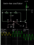
The twin-tee oscillator does what you want. One transistor, three capacitors. Increase frequency by increasing supply V.

twin-T oscillator 25MHz NPN VCO.png

- - - Updated - - -

Or change frequency by adjusting the potentiometer.
 
Thanks a lot, Bradthrad for your helpful replay. but, what about replacing the bipolar transistor by mosfet one?and what is the equation between the output frequency and the circuit parameters?

can you help me to answer the above questions?

- - - Updated - - -

Thanks a lot for this suggestion.
 

Mosfets have a measure of unpredictability. They are not all controlled in the same range of operation, to turn them On & Off. Some mosfets will not work at the low supply voltage of my simulation.

Furthermore an oscillator that doesn't work at a high supply voltage might start working if you reduce the supply voltage.

The twin-tee components usually have a 2:1 ratio among them, so that a particular frequency becomes the center frequency. Both of its T-shaped branches should carry about the same level of current, and have about the same voltage swings. Suitable figures are a few mA, and about 1 volt. These levels are sufficient to drive the transistor so that it gives the right amount of 'kick' to the circuit at the proper time.
 
Status
Not open for further replies.

Similar threads

Part and Inventory Search

Welcome to EDABoard.com

Sponsor

Back
Top