Continue to Site

Welcome to EDAboard.com

Welcome to our site! EDAboard.com is an international Electronics Discussion Forum focused on EDA software, circuits, schematics, books, theory, papers, asic, pld, 8051, DSP, Network, RF, Analog Design, PCB, Service Manuals... and a whole lot more! To participate you need to register. Registration is free. Click here to register now.

Finding RC constant of a complex RC circuit

Status
Not open for further replies.

prateek3790

Full Member level 2
Joined
Feb 8, 2016
Messages
131
Helped
1
Reputation
2
Reaction score
1
Trophy points
18
Activity points
1,190
finding rc constant of an complex rc circuit

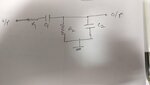
how to find the time constant of a complex circuit, which has many series and parallel components.please see the example circuit below.

can i convert the parallel components to series one using the q value transformation. and now since all are in series the time constant can be Req*Ceq.

Req = R1 + R2
Ceq = c1c2/(c1+c2)

also since i just want to calculate time constant does it matter from where the output is being taken.
 

Attachments

  • IMG_20180508_124628_01.jpg
    IMG_20180508_124628_01.jpg
    396 KB · Views: 116

Re: finding rc constant of an complex rc circuit

The high-pass low-pass combination has more than one "time constant", actually one zero and a pole pair (two real poles). There's no equivalent Req*Ceq.

Code:
        (C1 R2) s

Vo/Vi = -------------------------------------------------

        1 + (C1 R2 + C1 R1 + C2 R2) s + (C2 C1 R1 R2) s^2
 

Re: finding rc constant of an complex rc circuit

Hi,

... with the assumption that the source_impedance = 0 Ohms and the load_impedance is infinite.

Klaus
 

Re: finding rc constant of an complex rc circuit

The high-pass low-pass combination has more than one "time constant", actually one zero and a pole pair (two real poles). There's no equivalent Req*Ceq.

Code:
        (C1 R2) s

Vo/Vi = -------------------------------------------------

        1 + (C1 R2 + C1 R1 + C2 R2) s + (C2 C1 R1 R2) s^2

okay.
so among the two poles whichever is smaller that will dominate and will define the overall time constant.

but just for curiosity can you please tell why the above method is wrong. because suppose if it is possible to convert the parallel circuit to series one then in the overall circuit effectively there will be only one cap and one resistor.
 

Attachments

  • parallel_to_series.PNG
    parallel_to_series.PNG
    43.2 KB · Views: 110

Re: finding rc constant of an complex rc circuit

The parallel-series conversion is only valid for a single frequency.

To decide about dominant time constant. you need to specify actual RC values. I believe the meaning of "dominant" also changes with the pole/zero sequence.
 

Re: finding rc constant of an complex rc circuit

Hi,

I want to believe that by mentioning RC time constant the OP is talking about the circuit response to step change as regards DC operation.
 

Status
Not open for further replies.

Part and Inventory Search

Welcome to EDABoard.com

Sponsor

Back
Top