Continue to Site

Welcome to EDAboard.com

Welcome to our site! EDAboard.com is an international Electronics Discussion Forum focused on EDA software, circuits, schematics, books, theory, papers, asic, pld, 8051, DSP, Network, RF, Analog Design, PCB, Service Manuals... and a whole lot more! To participate you need to register. Registration is free. Click here to register now.

Optocoupler response time measurement

Status
Not open for further replies.

dhiraj.mahajan

Member level 1
Joined
May 29, 2017
Messages
38
Helped
0
Reputation
0
Reaction score
0
Trophy points
6
Activity points
265
hii
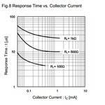
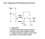
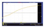
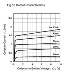
i have used RPI441C1E optocouplar for motor shaft position detection then respond time given in datasheet is 10us bur i have wark in 3.3V then actually respond time is 2ms can be see in digital scope i have required care-ct resistor value to minimum respond time ....cur-cut and respond graph is given in above plies Gide me
 

Attachments

  • Screenshot_1.jpg
    Screenshot_1.jpg
    31.8 KB · Views: 64
  • Screenshot_2.jpg
    Screenshot_2.jpg
    24.1 KB · Views: 104

Hi,

Show exactly your schematic (not a datasheet one), and include all your part values and voltages.
Then show a scope picture.

Klaus
 

hii
following is schematic and waveform
 

Attachments

  • IR sensor falling edge.JPG
    IR sensor falling edge.JPG
    171.9 KB · Views: 67
  • Screensho.jpg
    Screensho.jpg
    84.6 KB · Views: 76
  • IR sensor rising edge.JPG
    IR sensor rising edge.JPG
    168.8 KB · Views: 57

Hi,

Your schematic isn´t very helpful because:
* R6 is marked as "open" which makes no sense.
* input signal is unknown. --> scope picture missing.

R3 really is 33k? And you wonder why the output is slow?
The datasheet chart you posted suggests values 100R ... 1000R and you use 33 times the max suggested value...

Klaus
 

hii
but in scematic IR sensor output is given to sens output ic pin no. 3
and 33K R3 is assume for orating graph of Ic VS If
i have required Minimum current If=2mA will be drive then ...calculate RL resistor for above given graph
 

Attachments

  • Screenshot_3.jpg
    Screenshot_3.jpg
    29.4 KB · Views: 52

Hi,

give all informations at once, not piece by piece.

Instead of responding to my post you just gave new specifications..

--> decide what reponse time you need

Your initial question is about reponse time.
--> then use the "response time chart" of post#1.
You clearly see: the lower the resistor the better (faster) the response time.
Obviously a 33k resistor makes it vvveeerrrryyy slow.

--> then select the resistor according your estimated reponse time.

****
Next step: input current.
From the chart in post#6 you see that IC is about IF / 30.
With an IF of 2mA you may expect an IC of 65uA only. (Generally expect lower speed with lower current)

Now multiply this value with your load resistor to get the voltage amplitude.
You will recognize you need any amplifier or comparator for a suitable output signal.
Or choose another optocoupler.

Klaus
 

Multiplying the post #1 response times with factor 33 gives same rise/fall-time order of magnitude as in your measurement. Reducing R3 and R4 by a factor 10 seems appropriate at first sight.
 

What's the maximum speed of the motor and how accurately do you need to measure its shaft position?
That will determine how fast the opto needs to respond.
 

Status
Not open for further replies.

Similar threads

Part and Inventory Search

Welcome to EDABoard.com

Sponsor

Back
Top