pblanos
Newbie level 5
Hi to all,
I work on a Photoplethysmography (PPG) Project with a customised Optoelectronic Sensor to monitor vital signs where I acquire the signals (PPG + Accelerometer) from the sensor to a customised board for all the necessary analogue signal processing and through DAQs to LabVIEW for further processing to perform multi-channel Photoplethysmography (PPG).
I would like to convert this Opto-physiological Measurement System setup to a wireless (Bluetooth) one.
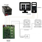
Please see the attached image of the current setup:

The current system consists of:
•An Opto-Electronic Sensor ( 7 channels: 4 different wavelengths, 1 photodiode cathode,1 photodiode anode and 1 GND) with 3-axis Accelerometer (5 Channels: 3 axis, 1 Voltage supply and 1 GND)
•an Electronics Board that implements a four-wavelength opto-physiological measurement system that provides all the necessary analogue signal processing to perform multi-channel Photoplethysmography (PPG).
•two Multifunction Data Acquisition USB Devices (DAQ, USB-6009, National Instruments Co., Novato, CA, USA) that provide basic DAQ functionality for the portable measurements and the Analogue-to Digital Conversion (ADC) for the captured PPG signals and the Accelerometer respectively.
•a power supply device, +15V (Dual Rail power supply, Rapid Electronics Ltd, Colchester, Essex, UK)
•a control and measurement software performed by LabVIEW GUI (National Instruments Co., USA)
Various connectors on the board:
① Power Supply Connectors: There are three power-supply connectors, VDD, -VDD and GND, standard banana plugs, which are colour coded (red = VDD, blue = -VDD, black = GND). The electronic board can be supplied with ±15V(nominal) when connected to the Power Supply Device mentioned above.
② RS232 Master Serial Port Connector: The MASTER connector is used to connect the Electronic Board to a PC. With a Serial-to-USB adapter cable it can be connected directly to a PC USB Port.
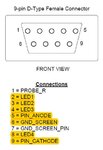
③ Probe Connector: The circuit uses a single 9-pin D-type female connector to connect to the Optoelectronic Sensor for the PPG signals capture.

The Accelerometer, on the other hand, is connected to a Data Acquisition USB Device which is in turn connected to a PC USB Port through a USB cable.
④ Processed Outputs:A single 16-way 0.1-inch pitch IDC connector is used as the output for all amplified and filtered output channels.
⑤ Raw Outputs: A single 16-way 0.1-inch pitch IDC connector is used as the output for the unprocessed output channels.
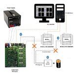
Please see the attached image of the Bluetooth setup:

Requirements:
•Bluetooth module on PPG sensor (7 channels)
•Bluetooth module to connect it to the serial probe connector to receive PPG signals from sensor
•Bluetooth module for Accelerometer signals (5 channels) either to DAQ or directly to labVIEW if ADC can be obtained
•Sampling frequency up to 256 Hz
•Battery to support Bluetooth module on sensor, Accelerometer and PPG signals.
I would appreciate any suggestions and ideas on how to convert my setup into a wireless one by eliminating at this stage the probe cable for more flexibility in order to avoid any disturbances on the acquired signals.
Thank you in advance
Panos
I work on a Photoplethysmography (PPG) Project with a customised Optoelectronic Sensor to monitor vital signs where I acquire the signals (PPG + Accelerometer) from the sensor to a customised board for all the necessary analogue signal processing and through DAQs to LabVIEW for further processing to perform multi-channel Photoplethysmography (PPG).
I would like to convert this Opto-physiological Measurement System setup to a wireless (Bluetooth) one.
Please see the attached image of the current setup:

The current system consists of:
•An Opto-Electronic Sensor ( 7 channels: 4 different wavelengths, 1 photodiode cathode,1 photodiode anode and 1 GND) with 3-axis Accelerometer (5 Channels: 3 axis, 1 Voltage supply and 1 GND)
•an Electronics Board that implements a four-wavelength opto-physiological measurement system that provides all the necessary analogue signal processing to perform multi-channel Photoplethysmography (PPG).
•two Multifunction Data Acquisition USB Devices (DAQ, USB-6009, National Instruments Co., Novato, CA, USA) that provide basic DAQ functionality for the portable measurements and the Analogue-to Digital Conversion (ADC) for the captured PPG signals and the Accelerometer respectively.
•a power supply device, +15V (Dual Rail power supply, Rapid Electronics Ltd, Colchester, Essex, UK)
•a control and measurement software performed by LabVIEW GUI (National Instruments Co., USA)
Various connectors on the board:
① Power Supply Connectors: There are three power-supply connectors, VDD, -VDD and GND, standard banana plugs, which are colour coded (red = VDD, blue = -VDD, black = GND). The electronic board can be supplied with ±15V(nominal) when connected to the Power Supply Device mentioned above.
② RS232 Master Serial Port Connector: The MASTER connector is used to connect the Electronic Board to a PC. With a Serial-to-USB adapter cable it can be connected directly to a PC USB Port.
③ Probe Connector: The circuit uses a single 9-pin D-type female connector to connect to the Optoelectronic Sensor for the PPG signals capture.

The Accelerometer, on the other hand, is connected to a Data Acquisition USB Device which is in turn connected to a PC USB Port through a USB cable.
④ Processed Outputs:A single 16-way 0.1-inch pitch IDC connector is used as the output for all amplified and filtered output channels.
⑤ Raw Outputs: A single 16-way 0.1-inch pitch IDC connector is used as the output for the unprocessed output channels.
Please see the attached image of the Bluetooth setup:

Requirements:
•Bluetooth module on PPG sensor (7 channels)
•Bluetooth module to connect it to the serial probe connector to receive PPG signals from sensor
•Bluetooth module for Accelerometer signals (5 channels) either to DAQ or directly to labVIEW if ADC can be obtained
•Sampling frequency up to 256 Hz
•Battery to support Bluetooth module on sensor, Accelerometer and PPG signals.
I would appreciate any suggestions and ideas on how to convert my setup into a wireless one by eliminating at this stage the probe cable for more flexibility in order to avoid any disturbances on the acquired signals.
Thank you in advance
Panos