Continue to Site

Welcome to EDAboard.com

Welcome to our site! EDAboard.com is an international Electronics Discussion Forum focused on EDA software, circuits, schematics, books, theory, papers, asic, pld, 8051, DSP, Network, RF, Analog Design, PCB, Service Manuals... and a whole lot more! To participate you need to register. Registration is free. Click here to register now.

Transient Analysis with AMS gives error

Status
Not open for further replies.

ashrafsazid

Advanced Member level 4
Joined
Sep 17, 2016
Messages
104
Helped
1
Reputation
2
Reaction score
2
Trophy points
18
Location
Germany
Activity points
935
Hi,

I have an ADC test bench where I have some transistor level blocks and one ctrl block. This CTRL block is written in both Verilog-A and Verilog-D code. when I perform an spectre simulation The ADC_testbench simulation is running okay, but when try to run it on AMS it gives the following error. N.B for ams simulation I am using verilog-D model of ctrl block and that didnt give me any parsing error.

ams.PNG
 

Describe correctly

This CTRL block is written in both Verilog-A and Verilog-D code.
when I perform an spectre simulation
The ADC_testbench simulation is running okay,
It can't be true.
Cadence Spectre can not treat Verilog-D.

but when try to run it on AMS it gives the following error.
Attached log is of Cadence Spectre.

N.B for ams simulation I am using verilog-D model of ctrl block
and that didnt give me any parsing error.
I can not understand what you want to mean at all.
 

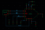
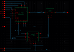
Hi, this are the attached figure. you can see there are several blocks. top level- input signals (verilogA) and ADC (has many subblocks, subblocks are CTRL, DelSIg, COI). Delsig - on Transistor level, CTRL & COI - has both verilogA and VerilogD.

adc_tb.PNG

adc_inside.PNG
When I run spectre, it takes verilogA model, and the whole testbench running fine without any error.

The verilogD codes written for CTRL and COI is tested with a testbench on Aldec Riviera, there it ran fine. Even when I generated a functional block for that CTRL & COI block on Cadence it gives no error during parsing (check and save) of the code.

So, when I start running an ams simulation in cadence configuring that CTRL & COI will run in VerilogD and Input in verilogA, Delta-Sigma on Transistor level, then I find some error regarding convergence problem, I assume that comes from analog/digital interface of the signal. But I tried changing timescale on VerilogD codes the problem doesnt solve.
 

Show me configuration view for the following states.

(1) For pure Spectre Simulation
(2) For AMS Simulation(Cosimulation between Spectre and NCSim)

I assume that comes from analog/digital interface of the signal.
But I tried changing timescale on VerilogD codes the problem doesnt solve.
There is no relation to timescale.

Do you surely set appropriate values for AtoD and DtoA ?

BTW, why do you short output bit buses ?

Output of COI is out<18:0>.
However you connect it to one node out.

I think COI is Decimation filter by CIC.
 
Last edited:

For pure spectre simulation there are no such config created- only a schematic view with schematic symbol for Delsig, VerilogA models for other block, then check and saved, then from ADE L, transient simulation is performed.


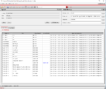
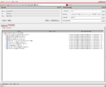
These are the config views for AMS.

aaaa_config1.PNG
aaaa_config2.PNG

I dont have idea about the- set appropriate values for AtoD and DtoA

- - - Updated - - -

BTW, why do you short output bit buses ?

Output of COI is out<18:0>.
However you connect it to one node out.

I think COI is Decimation filter by CIC.

The COI is just cascaded integrators simpler than CIC. the outputs are shorted, and hence the output pin is changed to inout so that this warning becomes suppressed.
 

@pancho_hideboo can you please tell me how to set the values for AtoD and DtoA
 

Status
Not open for further replies.

Part and Inventory Search

Welcome to EDABoard.com

Sponsor

Back
Top