Continue to Site

Welcome to EDAboard.com

Welcome to our site! EDAboard.com is an international Electronics Discussion Forum focused on EDA software, circuits, schematics, books, theory, papers, asic, pld, 8051, DSP, Network, RF, Analog Design, PCB, Service Manuals... and a whole lot more! To participate you need to register. Registration is free. Click here to register now.

Debugging KC705 board

Status
Not open for further replies.

beginner_EDA

Full Member level 4
Joined
Aug 14, 2013
Messages
191
Helped
0
Reputation
0
Reaction score
0
Trophy points
1,296
Activity points
3,854
Hi,
KC705 board suddendly stops working. fpga init_b pin glowing red instead of green and TI pin is not even glowing.
I tried to debug as here:
http://www.xilinx.com/support/answers/50079.html

and as mentioned in section 2a, TI Power controller need to be reprogrammed.
I downloaded the software from TI and try to load script as mentioned here:
http://www.xilinx.com/support/answers/56811.html

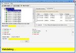
but software stuck at validating. see attachment.

The only difference I found is the fpga board has UCD 9240 chip where as default download for KC705, the script is for UCD9248.

Is there any solution?

- - - Updated - - -

I just found that fpga board also has same UCD9248. It was just misprinting in schematic design.
 

Attachments

  • pmbus.jpg
    pmbus.jpg
    159.5 KB · Views: 56

FPGA_INIT_B does not signify a problem with the power. You may have bricked the board trying to reprogram the TI power controller IC with a wrong xml script. Did you even verify that everything matched before attempting this?

If these LEDs above are not lit at power on, you might need to re-program the TI Power Controllers on your board. This can be done using the Texas Instruments Fusion Digital Power Manufacturing tool software package, the Texas Instruments USB Interface Adapter EVM, and the appropriate XML script.
For more details, see (Xilinx Answer 37561); and see (Xilinx Answer 56811) for information on the appropriate XML files to be used (these are board specific).
If you do not have a TI USB Interface Adapter EVM, you can follow the steps in (Xilinx Answer 54022) to order one.
Note the words highlighted in red...NOT LIT is the key. Your FPGA_INIT_B was lit, but was red, which signified the configuration failed not that the power failed.
 

ads-ee said:
Note the words highlighted in red...NOT LIT is the key. Your FPGA_INIT_B was lit, but was red, which signified the configuration failed not that the power failed.

If so how to fix configuration then?

waht is your clarification according to another one led (DS23 UCD Power controller power GND) is off which should not be as per above link? on board there is written TI for not glowing led.
 

Is DS23 off, before or after you attempted to reprogram the TI power controller?
 

You didm't answer the question.
Before?
After?
or both
 

yes before and after to reprogram the TI power controller, it is off. Actually have no impact on it.
 

there is no any way to debug in this stage??
 

You'll have to download the schematic for the board and start from the input power and start checking the power.

I could be the UCD9240 has failed.
 

Hi,
How I can download the schematic of the board when FPGA itself is not detectable in vivado? I assume you mean configuration file and not https://www.xilinx.com/support/documentation/boards_and_kits/kc705_Schematic_xtp132_rev1_1.pdf
Another thing where I can find Schematic for the board? could you please provide me any link if you already know to download?

What does Vivado detecting the FPGA have to do with debugging a board with the schematic of the board? Also you post a link of the schematic of the kc705 and then ask where can you get the schematic!?!?

You are a very confused person, to confused for me to help.
 
Status
Not open for further replies.

Part and Inventory Search

Welcome to EDABoard.com

Sponsor

Back
Top