Nethrapsgitech
Newbie level 4
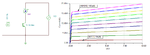
VI plot of the bipolar junction transistor using labview
I am trying to plot the VI characteristics of the Bipolar Junction transistor using Labview. I have swept the value of the collector emitter voltage. But to fix the value of the base current, I have fixed the base voltage. How to find the value of the base current that is fixed?.
I am trying to plot the VI characteristics of the Bipolar Junction transistor using Labview. I have swept the value of the collector emitter voltage. But to fix the value of the base current, I have fixed the base voltage. How to find the value of the base current that is fixed?.