Continue to Site

Welcome to EDAboard.com

Welcome to our site! EDAboard.com is an international Electronics Discussion Forum focused on EDA software, circuits, schematics, books, theory, papers, asic, pld, 8051, DSP, Network, RF, Analog Design, PCB, Service Manuals... and a whole lot more! To participate you need to register. Registration is free. Click here to register now.

Problem with output pwm wave form of TL494

Status
Not open for further replies.

tictac

Full Member level 5
Joined
Oct 22, 2006
Messages
297
Helped
3
Reputation
6
Reaction score
3
Trophy points
1,298
Location
Polland
Activity points
3,572
Hi
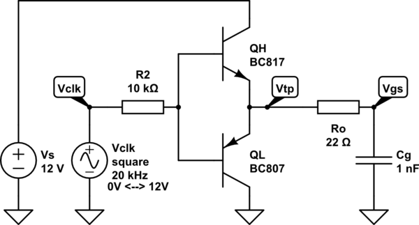
I want to adjust TL494 for one open-loop smps with 45% duty cycle and 100khz pwm on the output.
There is a problem with the output pwm wave form(pin9 & pin10). Rise time is about 500ns and fall time is about 2.5 us.
How can I correct the fall time? I think it is too high.

Its the schematic of tl494.Please help me for correcting the error .

tl494.png

Regards
 

Hi,

What about adding a resistor to GND?

Klaus
 

Hi,
I add two 220 ohm resistor from pin9 and pin10 to GND . But it didnt change .

- - - Updated - - -

Its the another section of my circuit.
pushpull.png
 

The rise/fall time values suggest that you are driving MOSFET gates or similar high capacitance load directly from TL494 output. That's a really bad idea. You need gate driver ICs or at least a discrete complementary emitter followers to achieve reasonable switching speed.
 
  • Like
Reactions: tictac

    tictac

    Points: 2
    Helpful Answer Positive Rating
Hi FvM
I use IRF2807. Can I use mosfet with lower drain-source current and lower input capacitance for better efficiency and without gate driver?
For example STD5NE10.
 

Hi,

A classical case of giving incomplete informations.
Why are the mosfets missing in post#1?....additionally they are not mentioned in the text...

Klaus
 

Sorry. I should give you all of information at first post.
 

Hi FvM
I use IRF2807. Can I use mosfet with lower drain-source current and lower input capacitance for better efficiency and without gate driver?
For example STD5NE10.

You may or you may not, depending whether Ids(max) is not exceeded during any of the circuit's operating conditions, which include overloads or other faults. Do you know the overload current value?

Perhaps it is better to add the classic PNP-transistor turnoff booster to the TL494 output?
 

The output power of my smps is about 1 watt. Vout=1000 volts .

Could you give me the schematic for your suggested solution,please?
 

As you know the maximum output power is about 1 watt. But the primary total current is about 1 ampere. I dont know why.

Below is the transformer specification:

Lp=290 uH , Np=10x2
Ls=1.4 H , Ns=700x1

The core is UU40/31 .
Ae=1.76 cm2
Bmax=0.2 Tesla

I think that the primary turns is low for 24 input voltage.

I use this equation

N=Vin*D*10^4/f*Ac*B

Vin-min=24 volts
D=%45
f(TL494)=100khz ==> f-core=50000
Ac=1.76 cm^2
B=0.2T

I dont know that can I purpose Vin=48 volts or Vin=24 volts??
The secondary winding of transformer is one section and primary winding is 2 section(2x10).
Please help me to reduce the primary current.

uu core.jpg

Regards
 

You have actually two threads in one. After the gate drive point has been (hopefully) clarified, you are shifting to transformer related problems.

Quite obviously the core isn't too small for 1 W. The peak core flux is even lower than calculated considering a symmetric waveform.

Most likely problem is winding capacitance and expectable transformer self resonance below the 50 kHz. Leakage inductance and primary Vds overvoltage might be also an issue.

I believe it would be much easier to implement the HV DC output using a cascade rectifier and respectively lower secondary number of turns. In any case you should make some measurements showing the actual current and voltage waveforms to see what's going on.
 

I believe it would be much easier to implement the HV DC output using a cascade rectifier and respectively lower secondary number of turns. In any case you should make some measurements showing the actual current and voltage waveforms to see what's going on.

Can you describe it a little more please?
I dont want use cockcroft-walton-generator. The output of smps must be very low noise and ripple.

Regards
 

Do you have access to a high-frequency current probe?

If not, beg, borrow or purchase one. We require to see the drain current waveforms.
Although your calculations indicate that the core SHOULD NOT saturate, we need to see the waveforms for sure.

Also, the drain-to-source voltage waveforms. Make sure that the scope probe HAS BEEN compensated, and that the scope's ground lead is connected with a very short wire directly to the source.

I also agree with FvM recommendation to lower the secondary output, and then use a voltage tripler to achieve the required voltage. That is the way that CRT color TVs were designed.

EDIT: please quantify the phrase: low ripple. How much is low ripple?
 

I dont have access to a high frequency current probe.
The desired ripple value is about 20mV. I have two low pass filter on the output to reduce the noise and ripple.
I think it is easier to replace mosfet with transistor. So, I replace IRF2807 with TIP122. Base connected to 120 ohm .one 100nf is parallel with 120 ohm. Emitter is connected to GND and collector is connected to the 10 ohm and it is connected to the primary transformer. But still the fall time is about 2us. Is it a proper solution?

Base_emitter waveform(two transistor)
base_emiter.jpg

base_emitter-collector_emitter(one transistor)
base_emitter-collector_emitter.jpg

collector_emitter(one transistor)
collector_emitter.jpg
 
Last edited:

The output of smps must be very low noise and ripple.
O.K., but I don't see how this requirement is related to not using a cascade rectifier topology.

But still the fall time is about 2us.
What do you consider as fall time? The base waveform shows rise and fall times in a 100 ns range. Apparently you are referring to the transformer wavefom. That's a matter of winding capacitance and not related to switch control or type of switches.

I suspect that your transformer + rectifier design simply isn't suited for 50 kHz operation.
 
  • Like
Reactions: tictac

    tictac

    Points: 2
    Helpful Answer Positive Rating
The output diode is BY8404 and is suited for frequency up to 25khz. So I remove all diodes(4) and connect one 1 M-ohm resistor to the secondary of transformer for testing. But the primary current still is about 1.1 ampere. I will decrease the switching frequency down to 20khz and I will test it tomorrow.
What is your idea about it?

Thanks you FvM
Regards.
 

The desired ripple value is about 20mV. I have two low pass filter on the output to reduce the noise and ripple.
I think it is easier to replace mosfet with transistor. So, I replace IRF2807 with TIP122.
]

Hmmm.
What makes you think that with a bipolar transistor the circuit will switch faster than a Mosfet?
 
  • Like
Reactions: tictac

    tictac

    Points: 2
    Helpful Answer Positive Rating
Yes . You are right. I will replace TIP122 with STD5NE10. what is your idea?
 

Mosfet gates must be driven both on and off. The TL494 cannot properly drive a MOSFET gate directly. The image in your first post will drive the MOSFETs on, but not off. A simple way to drive MOSFET gates from this IC is by using a PNP/NPN totem pole driver between the TL494's outputs and the gate of the FETs.


Something similar to this works quite well. The output from the TL494 would connect to VClk point and the MOSFET gate would connect at the Vgs point. You would need one of these circuits for each MOSFET. The capacitor Cg is only a representation of the MOSFET's gate capacitance and would not be part of the actual circuit. Obviously the type of PNP/NPN transistors and the resistor values in this circuit would be dependent upon the MOSFETs you're using and the amount of drive current required to turn them on/off at the speeds you require.
 
Last edited by a moderator:
  • Like
Reactions: tictac

    tictac

    Points: 2
    Helpful Answer Positive Rating
Status
Not open for further replies.

Similar threads

Part and Inventory Search

Welcome to EDABoard.com

Sponsor

Back
Top