davoud
Full Member level 2
Hello Everyone,
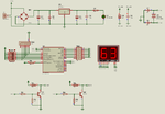
I am inexperienced in micro-controllers. I want read data from a "six-pin DIP switch" attached to the port A of PIC 16F876A and show data on two 7-segment display connected to port B and port C. I have a problem to read data.
Thanks.
My program :
I am inexperienced in micro-controllers. I want read data from a "six-pin DIP switch" attached to the port A of PIC 16F876A and show data on two 7-segment display connected to port B and port C. I have a problem to read data.
Thanks.
My program :
Code C - [expand]
Last edited by a moderator:

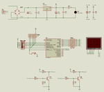
") and now my program work perfectly.
and now my program work perfectly.