gunterw
Newbie
- Joined
- Aug 28, 2015
- Messages
- 2
- Helped
- 0
- Reputation
- 0
- Reaction score
- 0
- Trophy points
- 1
- Location
- New Mexico
- Activity points
- 29
Here, listed for your convenience, Everything I can see as far as letters, references, or any other indications that would help identify the unit. All theses indications are on the pictures shown but may be difficult to read.
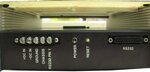
On the top: PILOT GP ADAPTOR 460V em 38-8 with a little circle with 4 lines at 12 3 6 and 9 hours.
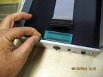
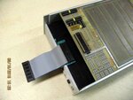
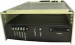
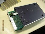
On the back: +DC IN -DC IN GROUND CHASSIS RS232 PIN 1 POWER RESET RS232
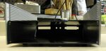
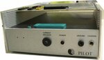
On the front: Current Breakers POWER GROUND CHASSIS PILOT and this sign that look like a Yin Yang circle.
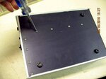
No writings on either side neither on the bottom
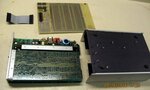
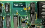
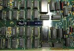
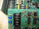
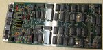
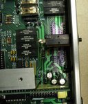
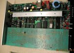
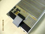
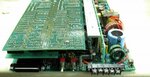
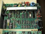
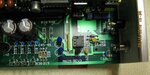
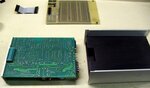
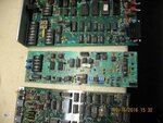
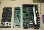
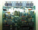
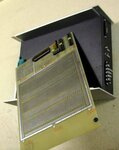
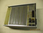
Inside the unit are a whole lot of electronic including a complex PWM power supply and what looks like a Z80 computer board with the Z80 processor.
I am quite certain this unit a some sort of EEPROM programmer from a UK company (by the spelling of ADAPTOR) but mainly I'd like to identify it so I can retrace the instructions and perhaps software to run it as intended.
On the top: PILOT GP ADAPTOR 460V em 38-8 with a little circle with 4 lines at 12 3 6 and 9 hours.
On the back: +DC IN -DC IN GROUND CHASSIS RS232 PIN 1 POWER RESET RS232
On the front: Current Breakers POWER GROUND CHASSIS PILOT and this sign that look like a Yin Yang circle.
No writings on either side neither on the bottom
Inside the unit are a whole lot of electronic including a complex PWM power supply and what looks like a Z80 computer board with the Z80 processor.
I am quite certain this unit a some sort of EEPROM programmer from a UK company (by the spelling of ADAPTOR) but mainly I'd like to identify it so I can retrace the instructions and perhaps software to run it as intended.
Attachments
-
 Assembly1.JPG28.5 KB · Views: 112
 -
 Attach.JPG32.9 KB · Views: 93
 -
 B5598.JPG45.1 KB · Views: 109
 -
 B5719REV3.JPG57.1 KB · Views: 120
 -
 B5781.JPG52.3 KB · Views: 107
 -
 B7519.JPG38.6 KB · Views: 106
 -
 Bottom1.JPG28 KB · Views: 102
 -
 Connector.JPG48.1 KB · Views: 105
 -
 Detached1.JPG42.2 KB · Views: 102
 -
 Empty.JPG21 KB · Views: 107
 -
 FlatWire.JPG40.5 KB · Views: 109
 -
 FlatWire2.JPG40.8 KB · Views: 106
 -
 Front.JPG18.3 KB · Views: 113
 -
 Front2.JPG20 KB · Views: 114
 -
 Inside.JPG32.6 KB · Views: 105
 -
 Main.JPG54.7 KB · Views: 102
 -
 MAINREV3.JPG30.5 KB · Views: 113
 -
 Open1.JPG33 KB · Views: 108
 -
 Parts1.JPG25.7 KB · Views: 112
 -
 Parts2.JPG49.9 KB · Views: 110
 -
 Parts3.JPG45.5 KB · Views: 124
 -
 PILOT1.JPG21.9 KB · Views: 114
 -
 Regulators.JPG53.3 KB · Views: 105
 -
 Separate.JPG34 KB · Views: 104
 -
 Top.JPG35.6 KB · Views: 105