Continue to Site

Welcome to EDAboard.com

Welcome to our site! EDAboard.com is an international Electronics Discussion Forum focused on EDA software, circuits, schematics, books, theory, papers, asic, pld, 8051, DSP, Network, RF, Analog Design, PCB, Service Manuals... and a whole lot more! To participate you need to register. Registration is free. Click here to register now.

Does higher Q factor leads to higher resonance frequency which means higher bandwidth

Status
Not open for further replies.

sys_eng

Full Member level 4
Joined
Aug 3, 2016
Messages
193
Helped
0
Reputation
2
Reaction score
1
Trophy points
18
Activity points
1,489
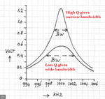
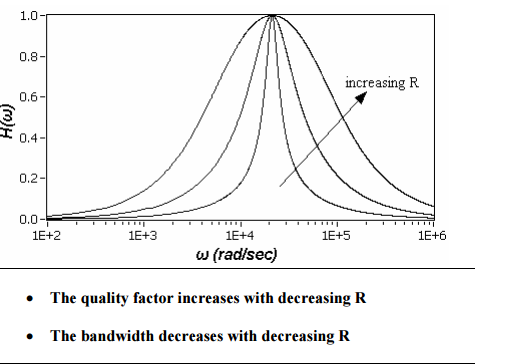
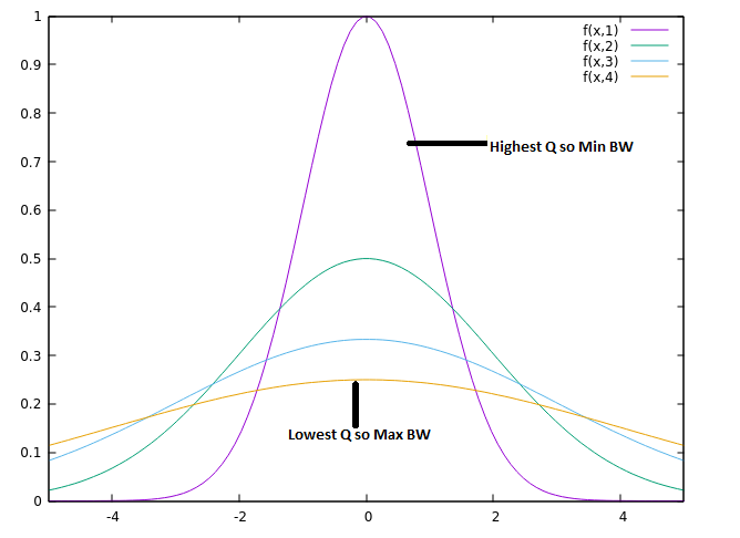
resonance frequency means imaginary impedance =0, and therefore highest power output.

Do you want resonance frequency as high as possible? which means higher bandwith?

what happen if operate system at resonance frequency? or higer than resonance frequency?
 

Resonance frequency means the frequency at which the oscillations will not be damped by the structure so energy will oscillate in it from electric to magnetic with no losses if the walls of structure are PEC. Resonance frequency is defined by the parameters of structure.
What happens if operated off resonance?
Oscillations will die out slowly due to structure.
Quality factor or Q value is defined as ratio of energy stored to the energy dissipated via walls of cavity so it is always desired to have a large Q factor. So to go to higher Q factors you have two options one is to reduce the losses in the walls that can be done by changing the material of walls with smaller losses. Other is to increase the stored energy in the cavity which is dictated by the resonance frequency which is further dictated by the structure of cavity.
The important point to keep in mind is that Resonance frequency is property of structure so if you want to change it then you have to modify the structure.
 

High Q causes a narrow bandwidth. At a higher frequency then you can have a wider modulation bandwidth.
 

High Q causes a narrow bandwidth. At a higher frequency then you can have a wider modulation bandwidth.

Can you please explain how Q factor is related to BW.
I agree that at higher frequency we can have wider modulation BW but nothing comes free as the frequency increases the size of components reduces so to design effective components at higher frequencies is equally devoted task.
 

Look in Google for the definition of the Q of an LC circuit. A high Q gives greater selectivity so the circuit selects only a few frequencies but rejects all other frequencies. A low Q circuit has poor selectivity so it selects many frequencies.
 

Attachments

  • Q.png
    Q.png
    182 KB · Views: 193

Look in Google for the definition of the Q of an LC circuit. A high Q gives greater selectivity so the circuit selects only a few frequencies but rejects all other frequencies. A low Q circuit has poor selectivity so it selects many frequencies.

so unless you want oscillaion, you do not want the circuit operates at resonance frequency, right?
 

A high Q gives greater selectivity so the circuit selects only a few frequencies but rejects all other frequencies. A low Q circuit has poor selectivity so it selects many frequencies.

The statement is correct but the graph is wrong. The curve with high Q will have narrow tails and the graph with low Q will have fat tails.

If the shape is not clear, the BW will be mostly defined as FWHM (full width at half maximum).
 

The statement is correct but the graph is wrong. The curve with high Q will have narrow tails and the graph with low Q will have fat tails.

??? The graph is wrong ???
 

The statement is correct but the graph is wrong. The curve with high Q will have narrow tails and the graph with low Q will have fat tails.

The graph is correct. Possibly you are referring to a graph with normalized amplitude.
 

Graph is correct the only difference is normalization. As BW is defined as Half Power so Higher Q graph has smaller BW as compared to Lower Q graph. Please correct me If I am wrong
 

Graph is correct the only difference is normalization. As BW is defined as Half Power so Higher Q graph has smaller BW as compared to Lower Q graph. Please correct me If I am wrong

Am I missing something here?

If I look at the high-Q graph, the peak is around 1.2 and the half-maximal value is around 0.6 and the full width at that value is about 4 kHz. Now take another look at the second graph and the peak is around 0.6 and the half value is 0.3 and the full width at 0.3 is around 0.7 kHz. The indicated BW is probably wrong unless drawn using some other rules. I agree qualitatively on this point.

I have some problem with the tails and I agree that I assumed the two graphs are normalized. If they are not, they will be difficult to compare.
 

Ok is this correct illustration of Q and BW?
As I get from the figure that BW will increase with increase in R so Quality factor will decrease.
I have one practical question. If we have a system like RF cavity which is operating at certain Q value and at a certain resonance (Resonance frequency is fixed). What changes we need to incorporate to operate it at higher Q and same resonance?
 

I believe a serious problem of this thread is that it doesn't discuss an actual problem. Each contributor is bringing in his own premises about the relevance of resonance, bandwidth and quality factor, assuming a certain, unfortunately unsaid application. A perfect method to talk on cross purposes.
 
  • Like
Reactions: LvW

    LvW

    Points: 2
    Helpful Answer Positive Rating
To get a higher Q, the coupling to external circuits must be reduced as they will load the circuit with a resistance as they absorb power, so reducing the circuit Q. Because of this the through loss will increase.
As not mentioned yet, for the highest Q the construction of the circuit must use the lowest loss components, such as silver plating or litz wire (depending on the frequency) and silver mica capacitors.
Frank
 

Ok is this correct illustration of Q and BW?

I beg to differ; they are not normalized and hence cannot be compared. Let me try to explain.

A system with high Q puts out most of the energy in a narrow frequency range. The peak is high and the width is narrow. But the total energy put out is normalized to 1.

Similarly a system with low Q will have the output spread out over much of the frequency range. The peak is low, the belly is fat and the total energy output is again normalized to 1.

The peak height is a measure of the Q. The FWHM is a measure of the bandwidth.

As others have explained already, the Q is dependent on the losses in the system (dissipation or frictional forces) and high Q system is made of low loss components. The loading need to be counted as loss or dissipation. Tight coupling makes for low Q systems.
 
In summary,
1)higher Q means better selectivity and narrower bandwidth
2)higher Q means less loss through parasitic resistance therefore oscillation will die out less
3)higher Q means less noise therefore more gain.
 

I really learned for this thread. Now I got idea how Q value is related to BW. Thanks all
 

I really learned for this thread. Now I got idea how Q value is related to BW. Thanks all

I plotted four normalized graphs but with different bandwidths and hence different Qs. I used normal distribution graph as model and used gnuplot to see...

 
Thanks for the effort. I have labelled the pic so please have a look and comment if I understood it rightly.


The loading need to be counted as loss or dissipation. Tight coupling makes for low Q systems.
When we talk of coupling then there comes yet another Q which is labelled as Q external. Rather coupling is defined by ratio of Q and Q external. So what is this Q external?
What you mean by tight coupling as I use following terminology
Under coupled coupling < 1
Critically coupled coupling = 1
Over coupled coupling > 1
 

When we talk of coupling then there comes yet another Q which is labelled as Q external. Rather coupling is defined by ratio of Q and Q external. So what is this Q external?

I was taught differently. Let me try to recollect.

1. Consider a harmonic oscillator (a mass connected to a spring with natural frequency f0)

2. You apply an external periodic force f to this mass (the force is applied only for small time to the mass connected with the spring)

3. The external mass will move with frequency f (forced vibration) but the energy transfer will be small- coupling comes here)

4. Slowly change f (start with smaller than f0 and go above f0) and observe the motion.

5. As the external frequency comes closer to f0, we see two changes: phase and amplitude.

6. Close to the f0, the oscillator absorbs energy from the external force field; the amplitude increases. The amplitude will be limited by the internal dissipation of the oscillator. (the absorption of energy)

7. The phase too changes: the phase difference between the external frequency and the natural frequency of the oscillator increases, then reaches a max, comes down to zero (at resonance) and then again goes through a maximum in the other direction. This is the dispersion spectrum.

Note: because of the coupling, the mass connected with a spring always moves with the external frequency but close to the natural frequency, it takes max energy from the external field.

Qualitatively, if the external force is applied for a short time (0.001 times the period), the coupling will be small. If the external force is applied for a long time (0.1 times the period), we will call the coupling large.

That was how I learnt.
 
Status
Not open for further replies.

Similar threads

Part and Inventory Search

Welcome to EDABoard.com

Sponsor

Back
Top