snmjack
Newbie level 4
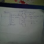
Hi, my name is swapnil. I am trying to make a water level controller using arduino. I refered many circuit ideas for different website and made my own design. Simulated it in Protues and it worked fine. Also i designed my PCB in eagle and started implementing.
Everything was going as per plan, but when i tried to test the input sensors voltage, i got major voltage drop due to water acting as resistance between the sensors.
For sensor - I used a PVC pipe, in which Cat 6 LAN cable is inserted. One wire of LAN cable is connected at bottom of PVC pipe with a stainless steel metal. This wire is also connected to 5V supply through board. Same way other sensors are connected to different levels of PVC pipes. Now when water rises till 1/4 tank full sensor, arduino will get the voltage at its digital input pins (Because of water, 5V sensor and 1/4 tank full sensor will get short).
Now the problem here is, water is conductive but with high resistance since its not much salty, so instead of getting 5V at 1/4 tank full sensor, i am getting around 2-3 volts.
My board is also ready and sensor set for both Below tank and overhead tank are both ready, and my program also works fine. but i am stuck at this voltage drop problem.
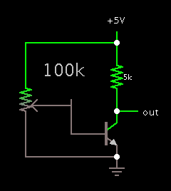
I had one thing in mind, what if i use a intermidiate circuit betweent he sensor set and board, which will detect any voltage above 0V and give output 5V. But i am not getting any such circuit ideas to build one.
Anyone have any idea.. how to tackle this problem.

