pisoiu
Advanced Member level 3
Hi all,
Maybe a lot of years ago my math was in better shape, but now it is gone, so I need some help.
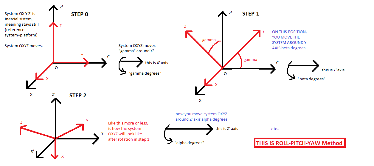
I need to rotate a coordinate system. I have an accelerometer which gives me accelerations on all 3 axes, X, Y, Z as 8 bit signed values. The accelerometer is mounted on a mobile platform but the accelerometer axis does not match the platform axis, so I need to rotate the X,Y,Z of the accelerometer into X', Y' and Z' of the platform, where let's say X' is the forward direction of the platform, Y' is side and Z' point towards earth.
From what I have been able to find over the net, the X', Y' and Z' can be calculated with the followinng formulas:
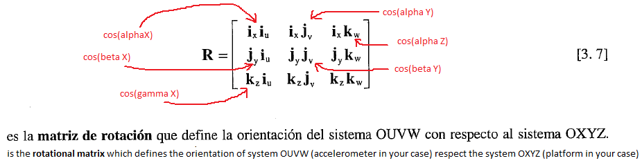
X'=X*cos(\[\alpha\]x)+Y*cos(\[\alpha\]y)+Z*cos(\[\alpha\]z)
Y'=X*cos(\[\beta\]x)+Y*cos(\[\beta\]y)+Z*cos(\[\beta\]z)
Z'=X*cos(\[\gamma\]x)+Y*cos(\[\gamma\]y)+Z*cos(\[\gamma\]z)
where \[\alpha\]x,y,z is the angle between X' platform axis and each accelerometer axis (X,Y,Z), \[\beta\]x,y,z is the angle between Y' platform axis and each accelerometer axis and similar for \[\gamma\]
between all these angles, there is a relation
\[\alpha\]x+\[\alpha\]y+\[\alpha\]z=\[\beta\]x+\[\beta\]y+\[\beta\]z=\[\gamma\]x+\[\gamma\]y+\[\gamma\]z=180o
also
\[\alpha\]x+\[\beta\]x+\[\gamma\]x=\[\alpha\]y+\[\beta\]y+\[\gamma\]y=\[\alpha\]z+\[\beta\]z+\[\gamma\]z=180o
In order to determine the coefficients (cos\[\alpha\],\[\beta\],\[\gamma\]..) two calibrations are required, first with 0 acceleration on X' and Y', leaving only Z'=1G (gravitational acceleration). This will determine the direction of Z' axis. A second calibration is required to determine the forward direction of the platform, X'. Then, knowing X' and Z', Y' should be possible to determine. The difference between these two calibration procedures, would be that for Z', the amount is known, it is 1G, but for X', the value will not be known.
The equations for calibration for non-moving platform should be:
X' : X1*cos(\[\alpha\]x)+Y1*cos(\[\alpha\]y)+Z1*cos(\[\alpha\]z)=0
Y' : X1*cos(\[\beta\]x)+Y1*cos(\[\beta\]y)+Z1*cos(\[\beta\]z)=0
Z' : X1*cos(\[\gamma\]x)+Y1*cos(\[\gamma\]y)+Z1*cos(\[\gamma\]z)=1G
where X1,Y1,Z1 are readouts from accelerometer when platform is not moving
The equation for calibration for forward accelerating platform should be
X' : X2*cos(\[\alpha\]x)+Y2*cos(\[\alpha\]y)+Z2*cos(\[\alpha\]z)=unknown constant
Y' : X2*cos(\[\beta\]x)+Y2*cos(\[\beta\]y)+Z2*cos(\[\beta\]z)=0
Z' : X2*cos(\[\gamma\]x)+Y2*cos(\[\gamma\]y)+Z2*cos(\[\gamma\]z)=1G
where X2,Y2,Z2 are readouts from accelerometer when platform is pushed forward
What I do not know is how to extract the coefficients (cos\[\alpha\],\[\beta\],\[\gamma\]) from calibration equations in order to use them into general X', Y' and Z' equations.
All the implementation will be done in 8bit assembly language, so the operations must be broken into what the CPU is able to do (8 bit add, subtraction, division and multiplication). The code to implement the general equations is already done, but the part with coefficients extractions is still a mistery.
Thanks.
Best regards,
Maybe a lot of years ago my math was in better shape, but now it is gone, so I need some help.
I need to rotate a coordinate system. I have an accelerometer which gives me accelerations on all 3 axes, X, Y, Z as 8 bit signed values. The accelerometer is mounted on a mobile platform but the accelerometer axis does not match the platform axis, so I need to rotate the X,Y,Z of the accelerometer into X', Y' and Z' of the platform, where let's say X' is the forward direction of the platform, Y' is side and Z' point towards earth.
From what I have been able to find over the net, the X', Y' and Z' can be calculated with the followinng formulas:
X'=X*cos(\[\alpha\]x)+Y*cos(\[\alpha\]y)+Z*cos(\[\alpha\]z)
Y'=X*cos(\[\beta\]x)+Y*cos(\[\beta\]y)+Z*cos(\[\beta\]z)
Z'=X*cos(\[\gamma\]x)+Y*cos(\[\gamma\]y)+Z*cos(\[\gamma\]z)
where \[\alpha\]x,y,z is the angle between X' platform axis and each accelerometer axis (X,Y,Z), \[\beta\]x,y,z is the angle between Y' platform axis and each accelerometer axis and similar for \[\gamma\]
between all these angles, there is a relation
\[\alpha\]x+\[\alpha\]y+\[\alpha\]z=\[\beta\]x+\[\beta\]y+\[\beta\]z=\[\gamma\]x+\[\gamma\]y+\[\gamma\]z=180o
also
\[\alpha\]x+\[\beta\]x+\[\gamma\]x=\[\alpha\]y+\[\beta\]y+\[\gamma\]y=\[\alpha\]z+\[\beta\]z+\[\gamma\]z=180o
In order to determine the coefficients (cos\[\alpha\],\[\beta\],\[\gamma\]..) two calibrations are required, first with 0 acceleration on X' and Y', leaving only Z'=1G (gravitational acceleration). This will determine the direction of Z' axis. A second calibration is required to determine the forward direction of the platform, X'. Then, knowing X' and Z', Y' should be possible to determine. The difference between these two calibration procedures, would be that for Z', the amount is known, it is 1G, but for X', the value will not be known.
The equations for calibration for non-moving platform should be:
X' : X1*cos(\[\alpha\]x)+Y1*cos(\[\alpha\]y)+Z1*cos(\[\alpha\]z)=0
Y' : X1*cos(\[\beta\]x)+Y1*cos(\[\beta\]y)+Z1*cos(\[\beta\]z)=0
Z' : X1*cos(\[\gamma\]x)+Y1*cos(\[\gamma\]y)+Z1*cos(\[\gamma\]z)=1G
where X1,Y1,Z1 are readouts from accelerometer when platform is not moving
The equation for calibration for forward accelerating platform should be
X' : X2*cos(\[\alpha\]x)+Y2*cos(\[\alpha\]y)+Z2*cos(\[\alpha\]z)=unknown constant
Y' : X2*cos(\[\beta\]x)+Y2*cos(\[\beta\]y)+Z2*cos(\[\beta\]z)=0
Z' : X2*cos(\[\gamma\]x)+Y2*cos(\[\gamma\]y)+Z2*cos(\[\gamma\]z)=1G
where X2,Y2,Z2 are readouts from accelerometer when platform is pushed forward
What I do not know is how to extract the coefficients (cos\[\alpha\],\[\beta\],\[\gamma\]) from calibration equations in order to use them into general X', Y' and Z' equations.
All the implementation will be done in 8bit assembly language, so the operations must be broken into what the CPU is able to do (8 bit add, subtraction, division and multiplication). The code to implement the general equations is already done, but the part with coefficients extractions is still a mistery.
Thanks.
Best regards,