Continue to Site

Welcome to EDAboard.com

Welcome to our site! EDAboard.com is an international Electronics Discussion Forum focused on EDA software, circuits, schematics, books, theory, papers, asic, pld, 8051, DSP, Network, RF, Analog Design, PCB, Service Manuals... and a whole lot more! To participate you need to register. Registration is free. Click here to register now.

Active magnetic loop automatic tuning

Status
Not open for further replies.

neazoi

Advanced Member level 6
Joined
Jan 5, 2008
Messages
4,123
Helped
13
Reputation
26
Reaction score
15
Trophy points
1,318
Location
Greece
Activity points
36,955
Hello this is a nice antenna http://www.techlib.com/electronics/antennas.html (the first schematic) I have tried.
It is a tuned loop and needs retuning every 5-10KHz or so. Tuning is done by varying the voltage to the varactor using the pot. Tuning is done by observing the strongest audio signal (noise) on the receiver that the antenna is connected to.

I Wonder if there is a clever trick one could use in order to automatically tune the antenna, mased on this noise?
 

'Perturb and observe' comes to mind, a strategy commonly used to find the maximum point of power transfer (MPPT). It seeks to find the optimum way to utilize a power source so as to obtain the most watts.

Suppose we had a 'black box' which does these steps:

1) Apply a certain voltage (1.2V) to the varactor.
2) Then add a slow up-and-down pulsation. Variation is a few percent.
3) Suppose signal strength increases at V=1.25 V. Then make that your new applied voltage.
4) Resume slow up-down pulsation.

The trick is to create a circuit whose response is not based on absolute signal strength, but by comparing to a 'recently remembered' level, however that can be accomplished.
 
  • Like
Reactions: neazoi

    neazoi

    Points: 2
    Helpful Answer Positive Rating
'Perturb and observe' comes to mind, a strategy commonly used to find the maximum point of power transfer (MPPT). It seeks to find the optimum way to utilize a power source so as to obtain the most watts.

Suppose we had a 'black box' which does these steps:

1) Apply a certain voltage (1.2V) to the varactor.
2) Then add a slow up-and-down pulsation. Variation is a few percent.
3) Suppose signal strength increases at V=1.25 V. Then make that your new applied voltage.
4) Resume slow up-down pulsation.

The trick is to create a circuit whose response is not based on absolute signal strength, but by comparing to a 'recently remembered' level, however that can be accomplished.

This was exactly what I was thinking of. From a predefined position, tune a bit higher or lower and observe the output voltage in both cases, related to the initial position. The one that is higher wins and you can go for it. Then repeat this procedure.

However, if the loop is tuned too far away, this procedure might be proven faulty or/and would require the above precedure to be performed for every part of the loop range arbitrary, until a point is found by chance. Also a feedback from the RX is needed, this can be audio feedback of course.

Do you have any related circuicity that could do this?

- - - Updated - - -

Now that I am thinking of it, a solar tracker accomplishes almost the same thing (however it uses two LDRs).
The problem is that if the solar panel is placed in the opposite direction of that of the sun rays, it will be hard to decide which way to go, right or left. This is the problem I describe above.
 
Last edited:

This sort of thing is done all the time by modern radios. You start the scan, the set scans the band at low sensitivity and if a suitable station is found you then memorise it on say channel1. Going for a scan again within a certain time (10 secs?), causes the set to increase its sensitivity and rescan, this normally has to be done four times or so before the set is running at its maximum sensitivity and a massive number of stations can be heard.
So you have a fast wide tuning scan, until a signal threshold is exceeded then you go into the perturb mode.
Frank
 
  • Like
Reactions: neazoi

    neazoi

    Points: 2
    Helpful Answer Positive Rating
This sort of thing is done all the time by modern radios. You start the scan, the set scans the band at low sensitivity and if a suitable station is found you then memorise it on say channel1. Going for a scan again within a certain time (10 secs?), causes the set to increase its sensitivity and rescan, this normally has to be done four times or so before the set is running at its maximum sensitivity and a massive number of stations can be heard.
So you have a fast wide tuning scan, until a signal threshold is exceeded then you go into the perturb mode.
Frank

Since only one frequency is needed to be "detected" (because the antenna is resonant in only one frequency), based on a preset noise threshold, I think it will be not too difficult to build a sawtooth generator and apply it's output voltage to the varicap directly, in order to scan the whole antenna range.

However, the sawtooth generator has to stop to a point (when AF or IF signal strength exceeds the preset threshold) and it's current output voltage to be kept there, in order for the scanning to stop.

Any ideas of how to implement such thing?

- - - Updated - - -

Now that I think of it better, I conclude to the next steps for a fully automatic tuning:

Set the desired gain of the preamplifier (one time set, by the user)
Set the desired threshold level (one time set, by the user)

1. Perform a full band scan until the output signal passes the preset threshold.
2a. If this threshold is passed, switch to perturb mode.
In perturb mode, lock to the near-by higher signal level, by comparing lower and higher frequency close-in levels.
If out of lock for any reason, repeat step 1.

How do you find this procedure?
 

Because of the high Q and the directivity of the aerial, I think you will miss some signals unless you are only after S9+40 ones. :)
Frank

No, I won't scan for any signals. I will scan until my receiver receives the highest volume of noise! This is the resonant frequency of the antenna.
 

That should "lock on" to some optimum tuning, but far away it will not be able to seek and find the sweet spot.

Its going to be completely deaf to large manual tuning changes, but could be a very useful gadget to have for final peaking.

The only way I can see of doing this would be to fit a potentiometer to the dial of the receiver to generate a voltage to indicate the receiver frequency setting.
Then use that voltage to access a lookup table that generated an output dc voltage to drive the varactor.

Brad's perturb and observe algorithm could possibly be used to make the system self learning so the lookup table will eventually fill itself in and continually improve and update itself.
 
  • Like
Reactions: neazoi

    neazoi

    Points: 2
    Helpful Answer Positive Rating
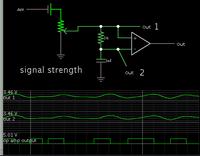
This project requires several building blocks. One is a detector for recent greatest signal strength.

Here is a circuit that detects when signal strength is rising. One input is delayed slightly by a capacitor. The output goes high only when signal strength is rising.

Output goes low when signal strength starts to decline. (The function is an integrator.)


This creates a window which might control something else, maybe a sample-and-hold, or some other memory circuit. It is not needed to remember greatest signal strength, but to record some other condition at the moment when signal strength starts to decline.

This is only a building block. More circuitry will need to be added.

Thanks for the help. This is useful if connected to the audio output of the receiver. A positive pulse means that the antenna resonance "frequency" has been found. However, to find exactly the peal (or near by), a second mode could be needed, following this one, as mentioned earlier. I think that the circuit could not be that complex, a kind of comparator, that tries to find the peak by comparing lower and higher amplitude variations. If you have anything in mind please let me know.
The only think I can think of is related to the puff-n-huff, but this is used for frequency variations.
 

The simplest practical solution I can think of would be to utilize a small MCU with a DAC and ADC. Generate a linear voltage ramp by counting up the value sent to the DAC and at each step read and store the ADC measurement of signal strength. It would build up a graph of tuning voltage vs. signal strength so the optimum point can be selected.

The other alternative would be to use a LOW power oscillator fed to the loop and optimize the SWR before switching back to receive mode. You say 'active magnetic loop' so I assume it is only for receiving, the technique doesn't lend itself to transmission except at very low power. From experience, loops can generate tens of KV at resonance even with only a few Watts drive so be careful if you try it.

Brian.
 
  • Like
Reactions: neazoi

    neazoi

    Points: 2
    Helpful Answer Positive Rating
The other alternative would be to use a LOW power oscillator fed to the loop and optimize the SWR before switching back to receive mode. You say 'active magnetic loop' so I assume it is only for receiving, the technique doesn't lend itself to transmission except at very low power. From experience, loops can generate tens of KV at resonance even with only a few Watts drive so be careful if you try it.
Brian.

You mean optimizing the SWR of the oscillator? But how can this help on tuning the loop?:bang:
 

What I was thinking was to disable the receiver temporarily and feed a signal TO the loop. If the signal is at the same frequency as you want to receive (or use the oscillator in a direct conversion receiver) you can use an SWR or simple voltage measurment to see when it's resonance has been achieved. It should be the same resonanace for radiating and receiving.

Brian.

Hm... I am missing something here. How will this lead to automatic tuning of the antenna?

Finding the loop resonance can be achieved by observing the audio noise out of the receiver that is connected to the loop. So why an oscillator is needed and how can this help?
 

Onlt that it gives a constant signal to use for tuning. Noise alone would be prone to picking up other sources. For example, if there was a stronger
noise source a few KHz away from the frequency you want, it might auto-tune to peak that instead.

I've never tried the DAC/ADC method but it would seem easy to build as an experiment. I'm thinking along the lines of an MCU and a dual op-amp to increase the tuning voltage range and also boost the incoming signal (AGC?) to the ADC. It would cost almost nothing and only need a few components. It would use a linear ramp rather than the 'Perturb and observe' method but the outcome should be the same. You would just sweep the voltage in small steps while looking at the signal strength then stop and backstep if the signal dropped from peak level.

Brian.
 
  • Like
Reactions: neazoi

    neazoi

    Points: 2
    Helpful Answer Positive Rating
Onlt that it gives a constant signal to use for tuning. Noise alone would be prone to picking up other sources. For example, if there was a stronger
noise source a few KHz away from the frequency you want, it might auto-tune to peak that instead.
That would seem to be a pretty fundamental obstacle to any " max amplitude" seeking tuning system.

If you were trying to resolve a weak signal next to a very powerful one, it might work directly against you.
 
  • Like
Reactions: neazoi

    neazoi

    Points: 2
    Helpful Answer Positive Rating
if I wanted to "tune" a resonant antenna with some sort of varactor based matching network, I would measure the reflection coefficient and either tune for a minimum reflection power, or tune for a zero degree reflection angle at the start of the matching network. You would use a diode power detector for the former, and a mixer/phase detector for the later. Odds are you would have to "sweep" the matching network varactor from 0V to 12V reverse biased, and have your control loop "stop" when it detected a match.
 
  • Like
Reactions: neazoi

    neazoi

    Points: 2
    Helpful Answer Positive Rating
I would measure the reflection coefficient and either tune for a minimum reflection power, or tune for a zero degree reflection angle at the start of the matching network
Which takes us full circle to my suggestion of using an oscillator as a signal source until the optimum tuning point is reached. :-D

Brian.
 

How about very loosely coupling a relatively strong wideband white noise source into the antenna, strong enough to override any strong slightly off frequency interfering signals, and peak on the noise.
You would need to insure the receiver was not totally overloaded, but the agc response should be a fair indication of when antenna resonance matched the receiver tuning.
 

I once used a RCA UHF signal strength meter that used some sort of vibrator to provide a comb of harmonics throughout the UHF band. You could hear its raucous buzz as you normalised the gain of the receiver. I am sure that a fast 1KHZ astable would give the same effect.
Frank
 

Status
Not open for further replies.

Part and Inventory Search

Welcome to EDABoard.com

Sponsor

Back
Top