Continue to Site
Follow along with the video below to see how to install our site as a web app on your home screen.
Note: This feature may not be available in some browsers.
What are issues of using buck converter rather than flyback converter ?
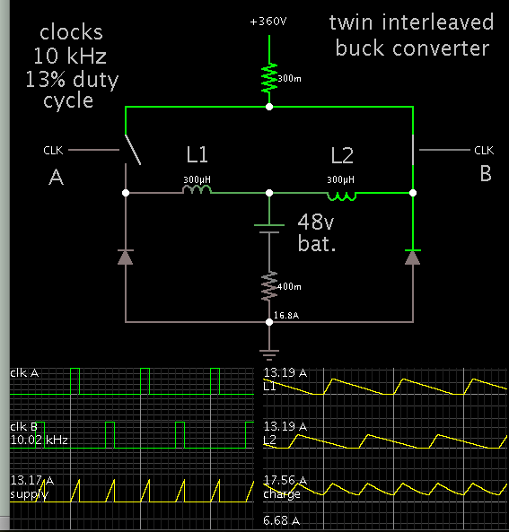
My buck converter (post #86) is only conceptual, of course. It carries a high voltage hazard to the batteries, since your power supply is hundreds of volts. It is possible for a spark to ignite hydrogen gas. For instance, when touching or disconnecting a clip from the battery terminal. Battery explosions have been known to happen.
Therefore I agree with the recommendations that you use a topology which provides isolation, and this implies a transformer.
for non sparking connection you generally need a high value resistor for pre-charge, with a relay to short the resistor when the voltages across the resistor are < 10V say...
Less than 10mV ripple is an unusual requirement for a battery charger.
Sir, The output load frequency is varying from 250 Hz to 40 kHz and the switching frequency is 100 kHz. I tried LC filter with the cut off freq from 50 to 100 Hz, but the settling time increases.The LC filter need to match the requirement.
Is this low frequency ripple at the switching frequency, or high narrow switching spikes ?
")