Continue to Site

Welcome to EDAboard.com

Welcome to our site! EDAboard.com is an international Electronics Discussion Forum focused on EDA software, circuits, schematics, books, theory, papers, asic, pld, 8051, DSP, Network, RF, Analog Design, PCB, Service Manuals... and a whole lot more! To participate you need to register. Registration is free. Click here to register now.

[SOLVED] scaling 0-10V to _10V to +10V using op amp

Status
Not open for further replies.

microcon555

Advanced Member level 4
Joined
Feb 13, 2009
Messages
108
Helped
9
Reputation
18
Reaction score
6
Trophy points
1,298
Activity points
1,877
I need to convert 0-10V signal to -10V to +10V

I dont know how to do it.

Can anybody guide me in this

Thanks in advance

Microcon
 

Hi,

U_out = -10V + 2 × U_in.

So gain = 2, output_offset = -10V

A simple solution is a difference opamp circuit. (Google for a schematic)
It has 4 connections:
* + input, connect you 0..10V input voltage here
* - input, connect GND here (= input reference voltage)
* output_reference, connect -10V (offset voltage here)
* output...obvious

The circuit has four resistors. Two on the input side, two at the output side (right).
Use 2 x 10k on the left side and 2 x 20 at the right side.

Klaus
 
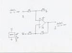
Try this :

voltageconverter.jpeg

Its a non inverting differential amplifier with a gain of x2
The inverting input needs to be held at +5v, there are various ways to do that, but probably the easiest would be a simple 5v regulator.

As the output needs to swing +/- 10v twelve volt supplies might work, but fifteen volts would be better.

*edit*

Klaus, you beat me by two minutes while I was drawing my circuit.
 
Hi,

This is a similar solution, same result...

U_out = 2 × (U_in - 5V)

Klaus
 

Tested the circuit by Warpspeed in simulation and found working correct.

Can 5V reference replaced with voltage dividers?

Thanks klaus and Warpspeed

Microcon
 

Hi,

Can 5V reference replaced with voltage dividers?
What voltage do you have?

If you use a voltage divider, then you need to take care about the total resistance.

Now it is 10 to 5V.
If you have 10V, then you need two 20k.

although they are connected in series, you must calculate as if they were connected in parallel.

R_total must be 10k. R_total = 1/ (1/R1 + 1/R2)

Klaus
 

Once again, Klaus has nailed it.

The resistor values of the voltage divider are important as well as the actual voltage division ratio.
This rather complicates things instead of simplification, because you are stuck with using standard available resistor values.

All things considered, the five volt regulator and 10K/20K resistors would still be my choice.
 

Yes, it seems keeping simple and less component count, i wish to go for voltage regulator

Thanks for both

Microcon
 

Hi,

If you need to buy a voltage regulator just for this...Then choose a voltage reference instead.
It is more precise and stable.
While a voltage regulator is built to supply circuitry with power, a voltage reference is meant for precise and reliable signal voltage.

If you use an ADC, then the best quality solution is to use just one voltage reference for both, the opamp circuit and the ADC.


Klaus
 

My circuit dont have ADC, it is just a converter.

Thanks for the advice, i'll use Voltage reference instead

Microcon
 

Status
Not open for further replies.

Part and Inventory Search

Welcome to EDABoard.com

Sponsor

Back
Top