Continue to Site
Follow along with the video below to see how to install our site as a web app on your home screen.
Note: This feature may not be available in some browsers.
Elaborate the problem. And give any associated information. Someone here might have an answer
The interface is activated by setting EXTRAM = 1
main.c(75): error C202: 'EXTRAM': undefined identifier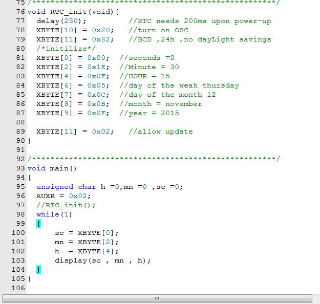
Probably unrelated if code-based problem. My 24-hr digital clock using CD4026 and seven-segment displays... the common cathode resistors when too low a value caused either the AND gates or the 4026s to count seconds and minutes up to 100 (no idea why??), using higher value resistors solved the problem.
Hi,
In my eyes it makes not much sense to use solution2 and 3 without true interrupts, but it is possible.
The flags in the registers in either case show the correct status.
For a "polling" solution I'd use solution 1.
Klaus
Hi,
What "shift problem"?
Describe the problem more detailed.
What do you do, step by step?
What do you expect?
And what do you see instead?
Klaus
Hi,
What "shift problem"?
Describe the problem more detailed.
What do you do, step by step?
What do you expect?
And what do you see instead?
Klaus
I can´t see an internal EEPROM.and write a flag in the internal eeprom
 V0 other than "010" may cause errors in time.
 Before writing the internal time, cal-
endar, and alarm registers, the SET bit in Register B
should be written to a logic one to prevent updates from
occurring while access is being attempted.
Hi,
Pleas confirm, that the time error is continous and not jumping.
(I mean if it is 60s per day it should be continously 2.5s per hour)
I can´t see an internal EEPROM.
You may READ register A to check if clock is initialized.
Take care when writing to register A.
Best: Never write to this register. Only at the very first time to start the clock.
An incidentally change in DV2
Also datasheet says:
Also, don´t write to the time / date registers, only when you want to set time. (once in half a year).
Klaus
void RTC_init(void){
	XBYTE[10] = 0x20; 	//turn on OSC
	XBYTE[11] = 0x92; 	//BCD ,24h ,no dayLight savings
	/*initilize*/
	XBYTE[0] = 0x00; 	//seconds =00
	XBYTE[2] = INITIAL_MINUTE; 	//Minute =
	XBYTE[4] = INITIAL_HOUR; 	//HOUR =
	XBYTE[6] = 0x03; 	    //day of the weak thursday
	XBYTE[7] = INITIAL_DAY; 	  //day of the month 12
	XBYTE[8] = 0x11; 	   //month = november
	XBYTE[9] = 0x15; 	  //year = 2015

	XBYTE[11] = 0x12; 	//allow update
}
/*****************************************************/
void main()
{
	unsigned char hr =0,min =0 ,sec =0,day=0,month=0,year=0;
	unsigned char initRTC_state ;
	bit disp_f = 0;
	delay(250);			//RTC needs 200ms upon power-up
	AUXR = 0x02;
	initRTC_state =	__api_rd_eeprom_byte(0x400);
	if( initRTC_state != VERSION_NO){
		RTC_init();    // use it at the first time only
		__api_wr_eeprom_byte(0x400, VERSION_NO);
	}
	while(1)
	{
	        sec = XBYTE[0];
	        min = XBYTE[2];
		hr  = XBYTE[4];
		day  = XBYTE[7];
		month= XBYTE[8];
		year = XBYTE[9];
		if(disp_f == 0){
			display(sec , min , hr);
			if(sec == 0x19)
				disp_f = 1;
		}
		else{
			display(year ,month ,day);
			if(sec == 0x39)
				disp_f = 0;
		}
	}
}