preethi19
Full Member level 5
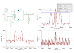
Hi i always thought AM modulation is nothing but we have a message and carrier signal. the modulated output is nothing but the carrier signal with changed amplitude while the carrier frequency remains same. pls see the two attached images

and

So frequency of carrier wave is constant
Frequency is the number of complete cycles per second. So for first image its fine to see carrier waves frequency constant because the msg signal freq is constant. But then say we have a random msg signal and the correspondence carrier signal. So now how we can see for 1 second and the number of complete cycles can vary depending on the message signal because carrier frequency is very irregular in the sense of having one proper complete cycle. So does frequency also change for AM modulation??? Also what is side bands. So i read "In radio communications, a sideband is a band of frequencies higher than or lower than the carrier frequency, containing power as a result of the modulation process. " so does the AM modulation process change carrier frequency resulting us to get some frequencies lesser than main carrier freq and a set greater than... Is my understanding right or are sidebands something we add intentionally or does it automatically come to exist after modulation???? why asking this is becoz i see classifications of single side band, double side band-SC(with no carrier). So can see in a way we can choose what we want to use for the side bands. but then in the above quoted "as a result of modulation" so does this happen automatically????? Pls help
and
So frequency of carrier wave is constant
Frequency is the number of complete cycles per second. So for first image its fine to see carrier waves frequency constant because the msg signal freq is constant. But then say we have a random msg signal and the correspondence carrier signal. So now how we can see for 1 second and the number of complete cycles can vary depending on the message signal because carrier frequency is very irregular in the sense of having one proper complete cycle. So does frequency also change for AM modulation??? Also what is side bands. So i read "In radio communications, a sideband is a band of frequencies higher than or lower than the carrier frequency, containing power as a result of the modulation process. " so does the AM modulation process change carrier frequency resulting us to get some frequencies lesser than main carrier freq and a set greater than... Is my understanding right or are sidebands something we add intentionally or does it automatically come to exist after modulation???? why asking this is becoz i see classifications of single side band, double side band-SC(with no carrier). So can see in a way we can choose what we want to use for the side bands. but then in the above quoted "as a result of modulation" so does this happen automatically????? Pls help
Last edited: