pic.programmer
Advanced Member level 3
Hi
I have used PIC16F877A @ 4 MHz external crystal. I have used Dany's PID Library posted at libstock.
http://www.libstock.com/projects/view/161/pid-library
The mikroC PRO PIC library contains only 3 functions and the mikroPascal PRO PIC library contains 5 functions. So, I have ported mikroPascal PRO PIC PID Library to mikroC PRO PIC.
I want to know have I successfully ported the PID Library to C ?
If the mikroPascal PRO PIC library (.mkpg) file is installed using the mikroE Package Manager then it creates a Packages\PID Library\Examples folder in the Compiler folder. It contains two zipped files which are examples of using the Library. I have used the code of one of the examples to test the Library but I am not sure whether the Library has been successfully ported to C or not.
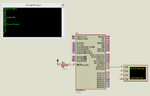
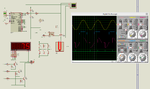
I am posting the screenshot (Proteus simulation) of the project. Is the values it is showing correct ?
I have used PIC16F877A @ 4 MHz external crystal. I have used Dany's PID Library posted at libstock.
http://www.libstock.com/projects/view/161/pid-library
The mikroC PRO PIC library contains only 3 functions and the mikroPascal PRO PIC library contains 5 functions. So, I have ported mikroPascal PRO PIC PID Library to mikroC PRO PIC.
I want to know have I successfully ported the PID Library to C ?
If the mikroPascal PRO PIC library (.mkpg) file is installed using the mikroE Package Manager then it creates a Packages\PID Library\Examples folder in the Compiler folder. It contains two zipped files which are examples of using the Library. I have used the code of one of the examples to test the Library but I am not sure whether the Library has been successfully ported to C or not.
I am posting the screenshot (Proteus simulation) of the project. Is the values it is showing correct ?