milan.rajik
Banned
@FvM
I will check.
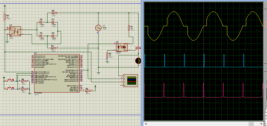
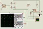
Here is my Timer interrupt based TRIAC control. Fires triac after 5 ms for 50 Hz AC. buttons are not programmed yet.
- - - Updated - - -
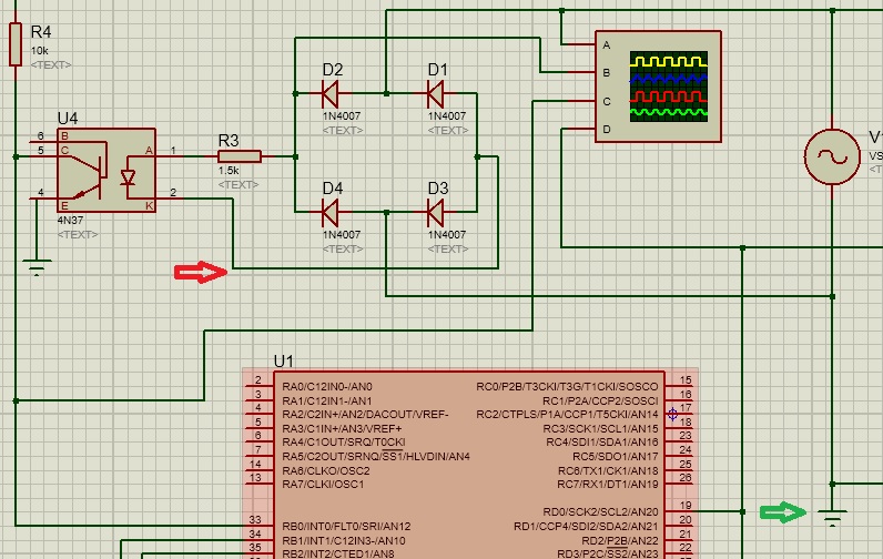
I have connected the junction where diodes D4 and D3 meets to GND. Is it causing the bridge to function only for half of AC ? I had to use GND because without GND connected to VSINE it doesn't simulate and gives GMIN step error.
I will check.
Here is my Timer interrupt based TRIAC control. Fires triac after 5 ms for 50 Hz AC. buttons are not programmed yet.
- - - Updated - - -
I'm not using Proteus 8 and can't check your simulation setup. But obviously the 4n37 output waveform (about 50 Hz square wave with 50 percent duty cycle) is different from the expectable 100 Hz pulses. It may be something trivial like interchanged pins in the simulation model. You can find out by e.g. reviewing a SPICE netlist of the design.
I have connected the junction where diodes D4 and D3 meets to GND. Is it causing the bridge to function only for half of AC ? I had to use GND because without GND connected to VSINE it doesn't simulate and gives GMIN step error.